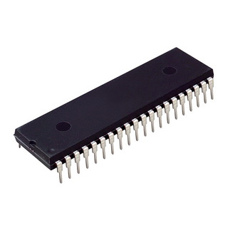
PIC16F877A-I/P Microcontroller MCUs/MPUs/SOCs 14KB 4V~5.5V 20MHz FLASH 33 DIP-40
EGP 220
See other suppliers →Description
PIC16F877A-I/P Microcontroller MCUs/MPUs/SOCs 14KB 4V~5.5V 20MHz FLASH 33 DIP-40 The PIC16F877A-I/P is a popular 8-bit microcontroller from Microchip Technology, widely used in embedded systems and automation applications. Housed in a DIP-40 (Dual Inline Package with 40 pins), this device offers a rich set of features that make it ideal for both beginner and professional level designs. It features 14KB of Flash program memory, 368 bytes of RAM, and 256 bytes of EEPROM, enabling storage of both application code and non-volatile data. The microcontroller operates within a voltage range of 4.0V to 5.5V and can run at clock speeds of up to 20MHz, providing a good balance between performance and power consumption. The PIC16F877A-I/P is equipped with 33 I/O pins, making it suitable for applications that require a high number of input/output lines. Additionally, it includes a wide array of peripherals such as USART, SPI, I2C, and PWM modules, as well as 8-channel 10-bit ADC (Analog-to-Digital Converter), timers, and watchdog timers for reliability. Its robust feature set and ease of programming using MPLAB IDE and PICkit programmers make the PIC16F877A-I/P a versatile and reliable choice for applications such as industrial control systems, robotics, home automation, and educational projects. Features: CPU 8-bit PIC Number of Pins 40 Operating Voltage (V) 4 to 5.5 V Number of I/O pins 33 ADC Module 8ch, 10-bit Timer Module 8-bit(2), 16-bit(1) Comparators 2 DAC Module Nil Communication Peripherals UART(1), SPI(1), I2C(1), MSSP(SPI/I2C) External Oscillator Up to 20Mhz Internal Oscillator Nil Program Memory Type Flash Program Memory (KB) 14KB CPU Speed (MIPS) 5 MIPS RAM Bytes 368 Data EEPROM 256 bytes Specifications: CPU 8-bit PIC Architecture 8 Program Memory Size (Kbytes) 14 RAM (bytes) 368 EEPROM/HEF 256/HEF Pin Count 40 Max. CPU Speed (MHz) 20 Peripheral Pin select (PPS) No Internal Oscillator No No. Of comparators 2 No. Of Operational Amplifier 0 No. Of ADC channels 14 Max ADC Resolution (bits) 10 ADC with Computation No Number of DAC Converter 0 Max DAC resolution 0 Internal Voltage Reference Yes Zero Cross Detect No No. Of 8-bit timers 2 No. Of 16-bit Timers 1 Signal Measurement Timer 0 Hardware Limit Timer 0 No. Of PWM outputs 0 Max PWM resolution 10 Angular Timer No Math Accelerator No No. Of UART module 1 No. Of SPI Module 1 No. Of I2C module 1 No. Of USB Module 0 Windowed Watchdog Timer (WWDT) No CRC/Scan No Numerically Controlled Oscillator 0 Cap. Touch Channels 11 Segment LCD 0 Minimum Operating Temperature (*C) -40 Maximum Operating Temperature (*C) 125 Minimum Operating Voltage (V) 4 Maximum Operating Voltage (V) 5.5 High Voltage Capable No Pinout Configuration: Pin Number Pin Name Description 1 MCLR/Vpp MCLR is used during programming, mostly connected to programmer like PicKit 2 RA0/AN0 Analog pin 0 or 0 th pin of PORTA 3 RA1/AN1 Analog pin 1 or 1 st pin of PORTA 4 RA2/AN2/Vref- Analog pin 2 or 2 nd pin of PORTA 5 RA3/AN3/Vref+ Analog pin 3 or 3 rd pin of PORTA 6 RA4/T0CKI/C1out 4 th pin of PORTA 7 RA5/AN4/SS/C2out Analog pin 4 or 5 th pin of PORTA 8 RE0/RD/AN5 Analog pin 5 or 0 th pin of PORTE 9 RE1/WR/AN6 Analog pin 6 or 1 st pin of PORTE 10 RE2/CS/AN7 7 th pin of PORTE 11 Vdd Ground pin of MCU 12 Vss Positive pin of MCU (+5V) 13 OSC1/CLKI External Oscillator /clock input pin 14 OSC2/CLKO External Oscillator /clock output pin 15 RC0/T1OSO/T1CKI 0 th pin of PORT C 16 RC1/T1OSI/CCP2 1 st pin of POCTC or Timer/PWM pin 17 RC2/CCP1 2 nd pin of POCTC or Timer/PWM pin 18 RC3/SCK/SCL 3 rd pin of POCTC 19 RD0/PSP0 0 th pin of POCTD 20 RD1/PSPI 1 st pin of POCTD 21 RD2/PSP2 2 nd pin of POCTD 22 RD3/PSP3 3 rd pin of POCTD 23 RC4/SDI/SDA 4 th pin of POCTC or Serial Data in pin 24 RC5/SDO 5 th pin of POCTC or Serial Data Out pin 25 RC6/Tx/CK 6 th pin of POCTC or Transmitter pin of Microcontroller 26 RC7/Rx/DT 7 th pin of POCTC or Receiver pin of Microcontroller 27 RD4/PSP4 4 th pin of POCTD 28 RD5/PSP5 5 th pin of POCTD 29 RD6/PSP6 6 th pin of POCTD 30 RD7/PSP7 7 th pin of POCTD 31 Vss Positive pin of MCU (+5V) 32 Vdd Ground pin of MCU 33 RB0/INT 0 th pin of POCTB or External Interrupt pin 34 RB1 1 st pin of POCTB 35 RB2 2 nd pin of POCTB 36 RB3/PGM 3 rd pin of POCTB or connected to programmer 37 RB4 4 th pin of POCTB 38 RB5 5 th pin of POCTB 39 RB6/PGC 6 th pin of POCTB or connected to programmer 40 RB7/PGD 7 th pin of POCTB or connected to programmer Applications: Multiple DIY Projects. Very good choice if you are learning PIC. Projects requiring Multiple I/O interfaces and communications. Replacement for Arduino Module. Ideal for more advanced level A/D applications in automotive, industrial, appliances and consumer applications. Package Contents: 1 X PIC16F877A-I/P Microcontroller MCUs/MPUs/SOCs 14KB 4V~5.5V 20MHz FLASH 33 DIP-40 Datasheet: PIC16F877A Microcontroller
From the supplier's page.
makhzan doesn't sell — every offer opens the supplier's own site.