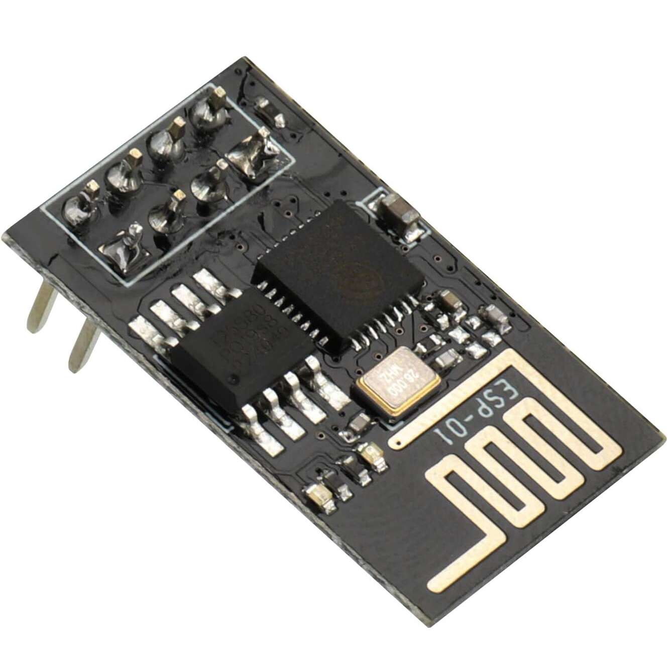
WiFi ESP8266-ESP01 Serial TTL Module
EGP 90
See other suppliers →Description
WiFi ESP8266-ESP01 Serial TTL Module The ESP8266 ESP‑01 is a highly compact WiFi module that provides both serial‑to‑WiFi bridging and full standalone microcontroller operation. It employs a 32‑bit Tensilica Xtensa LX106 microprocessor running typically at 80 MHz (and supporting up to ~160 MHz) to deliver built‑in WiFi capabilities and integrated TCP/IP networking functionality. Key Features of ESP8266 ESP-01 WIFI MODULE: 32‑bit Tensilica Xtensa LX106 processor core for onboard computing. WiFi IEEE 802.11 b/g/n connectivity and full TCP/IP stack support. 1 MByte (8 Mbit) external flash memory typical. Two GPIO pins exposed (GPIO0, GPIO2) for peripherals or external signalling. Serial UART interface (TX/RX) for communication or programming. Operates from 3.0‑3.6 V (nominal 3.3 V) power supply. Supports multiple operating modes: Station (STA), Access Point (AP), and combined AP+STA. Specifications: Supply voltage: 3.3 V The working voltage of leads: 3.3 V Current consumption up to 300 mA Supports standard wi-fi – wi-fi 802.11 b, g, n Operates in the 2.4 GHz frequency Supports WPA / WPA2 protection Can work in AP mode (Access Point), STA (standalone) and AP+STA Transmitter power: 19,5 dBm Supports AT commands Has a built-in Flash memory: 1 MB Communication via the serial UART interface Has a built-in PCB antenna Equipped with communication interfaces: SPI, UART, SDIO Has 8 leads pitch of 2 mm 3 x GPIO – digital outputs/inputs Mounting: through the hole – pitch 2,54 (gold pin connectors) Dimensions: 24 x 14 mm Pin Configuration: The module has 8 pins output on the two-row (2×4) gold pin strip raster 2.54 mm. PIN DESCRIPTION Vcc Power supply 3.3 V, current consumption up to 300 mA. GND The mass of the system. Tx The transmitter of the serial interface UART. Rx The receiver of the serial interface UART. RST Reset system – activated by low state. In a mode of regular operation, specify high state 3.3 V. CH_PD Power down – indicating low state causes a transition to sleep mode. For software updates and communication via the UART, you must specify the high state 3.3 V. GPIO0 Lead GPIO number 0. To update software, you must indicate the low status (connect to GND). GPIO2 Lead GPIO number 2. Applications: Add WiFi connectivity (serial‑to‑WiFi bridge) to microcontroller systems such as Arduino or STM32. Use as a standalone WiFi‑enabled microcontroller for IoT nodes, sensor hubs or home automation. Remote telemetry, data logging, wireless sensor networks and embedded control systems. Rapid prototyping of WiFi‑based devices, connecting to cloud or local networks. Educational projects and maker applications requiring low‑cost wireless connectivity. RESOURCES: ESP8266EX Datasheet
From the supplier's page.
makhzan doesn't sell — every offer opens the supplier's own site.