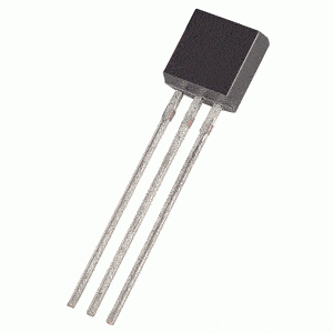
2N3904 40V 625mW 100@10mA,1V 0.2A NPN TO-92 Bipolar Transistor
EGP 1
See other suppliers →Description
2N3904 Pin Configuration Pin Number Pin Name Description 1 Emitter Current Drains out through the emitter 2 Base Controls the biasing of transistor 3 Collector Current flows in through the collector Features Bi-Polar NPN Transistor DC Current Gain (hFE) is 300 maximum Continuous Collector current (IC) is 200mA Base- Emitter Voltage (VBE) is 6V Collector-Emitter Voltage (VCE) is 40V Collector-base voltage (VCB) is 60V Available in To-92 Package Note: Complete Technical Details can be found at the 2N3904 datasheet given at the end of this page. Brief Description on 2N3904: 2N3904 is an NPN transistor hence the collector and emitter will be left open (Reverse biased) when the base pin is held at the ground and will be closed (Forward biased) when a signal is provided to the base pin. 2N3904 has a gain value of 300; this value determines the amplification capacity of the transistor. The maximum amount of current that could flow through the Collector pin is 200mA, hence we cannot connect loads that consume more than 200mA using this transistor. To bias a transistor we have to supply current to the base pin, this current (IB) should be limited to 5mA. When this transistor is fully biased it can allow a maximum of 200mA to flow across the collector and emitter. This stage is called Saturation Region and the typical voltage allowed across the Collector-Emitter (VCE) or Collector-Base (VCB) could be 40V and 60V respectively. When the base current is removed the transistor becomes fully off, this stage is called the Cut-off Region and the Base Emitter voltage could be around 600 mV. 2N3904 as switch: When a transistor is used as a switch it is operated in the Saturation and Cut-Off Region as explained above. As discussed, a transistor will act as an Open switch during Forward Bias and as a closed switch during Reverse Bias, this biasing can be achieved by supplying the required amount of current to the base pin. As mentioned the biasing current should maximum of 5mA. Anything more than 5mA will kill the Transistor; hence a resistor is always added in series with base pin. The value of this resistor (RB) can be calculated using the below formulae. RB = VBE / IB Where, the value of VBE should be 5V for 2N3904 and the Base current (IB depends on the Collector current (IC). The value of IB should not exceed mA. 2N3904 as Amplifier: A Transistor acts as an Amplifier when operating in an Active Region . It can amplify power, voltage, and current in different configurations. Some of the configurations used in amplifier circuits are: Common emitter amplifier Common collector amplifier Common base amplifier Of the above types, the common emitter type is the most popular and most used configuration. When used as an Amplifier the DC current gain of the Transistor can be calculated by using the below formulae DC Current Gain = Collector Current (IC) / Base Current (IB) Applications: Driver Modules like Relay Driver, LED driver, etc… Amplifier modules like Audio amplifiers, signal Amplifiers, etc… VCB and VBE are high and hence can be used to control voltage loads up to 40V Commonly used in TV and other home appliances 2N3904 Transistor Datasheet
From the supplier's page.
makhzan doesn't sell — every offer opens the supplier's own site.