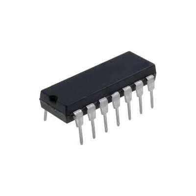
LM339 Quad Differential Comparator PDIP-14
EGP 10
See other suppliers →Description
LM339 Quad Differential Comparator PDIP-14 The LM339 Quad Differential Comparator PDIP-14 is a four-channel voltage comparator featuring wide supply capability, low quiescent current, low input bias and offset, and open-collector outputs designed for wired-AND connections and level-shifting to TTL, MOS, and CMOS logic families, supplied in a PDIP-14 through-hole package for prototyping and retrofit applications. LM339 is manufactured by many industries. The devices consist of four independent voltage comparators that are designed to operate from a single power supply. Also operation from dual supplies is possible, as long as the difference between the two supplies is 2 V to 36 V. LM339 is used in applications where a comparison between two voltage signals is required. In addition with four of those comparators on board the device can compare four pairs of voltage signals at a time which comes in handy in some applications. The comparator is popular among makers and engineers for being low cost and good performance. The device response is also fast enough to satisfy many applications. Features Single-supply operation from 2-30V and dual-supply operation from ±1V to ±18V allowing flexible system integration. Low supply-current drain independent of supply voltage with typical supply current of 0.8mA. Low input bias current and offset current for precision comparisons with typical input bias current of 25nA and input offset current of 3nA. Low input offset voltage for accurate threshold detection with typical VIO≈2mV. Open-collector outputs compatible with TTL, MOS, and CMOS logic for wired-AND configurations. Common-mode input range includes ground for single-supply systems. Wide operating temperature and device options for industrial and commercial use. Available in PDIP-14 through-hole package for easy breadboard and PCB prototyping. PINOUT Pin Name Description 1 1OUT Output pin of the comparator 1 2 2OUT Output pin of the comparator 2 3 VCC Power supply 4 2IN- Negative input pin of the comparator 2 5 2IN+ Positive input pin of the comparator 2 6 1IN- Negative input pin of the comparator 1 7 1IN+ Positive input pin of the comparator 1 8 3IN- Negative input pin of the comparator 3 9 3IN+ Positive input pin of the comparator 3 10 4IN- Negative input pin of the comparator 4 11 4IN+ Positive input pin of the comparator 4 12 GND Ground 13 4OUT Output pin of the comparator 4 14 3OUT Output pin of the comparator 3 User Guide First let us consider the internal connection of four comparators in the device as shown below. Now let us take a single comparator from the four and construct a simple application circuit as show below. Here the comparison between voltages V1 and V2 is done by the device and an output is provided as Vo. Also the device is powered from single voltage source of VCC as shown above. In the circuit the comparison output goes as: If V1>V2 then Vo = VCC If V2>V1 the Vo = 0V or GND Based on the state of the output we can determine whether V1 is higher or V2 is higher at the input. Applications Window comparators, zero-cross detectors, and threshold detection circuits. Level translation and logic interfacing using open-collector outputs. Power supervision, battery monitoring, and undervoltage/overvoltage detection. Oscillators, peak detectors, and pulse-shaping circuits. Educational electronics, prototyping, and legacy PDIP-based designs. Documents Datasheet CAD Files
From the supplier's page.
makhzan doesn't sell — every offer opens the supplier's own site.