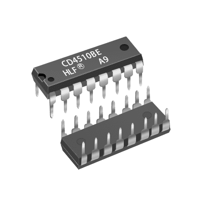
CD4510BE Positive Edge Counter/Divider 3V~18V 11MHz PDIP-16
EGP 25
See other suppliers →Description
CD4510BE Positive Edge Counter /Divider 3V~18V 11MHz PDIP-16 The CD4510B, manufactured by Shenzhen Honglifa Electronics Co., Ltd., is a presettable BCD up/down counter with four synchronously clocked D-type flip-flops. It features T-type flip-flop functionality, and counters can be reset or preset via external inputs. The CD4510B will count out of non-BCD counter states in a maximum of two clock pulses in the up mode, and a maximum of four clock pulses in the down mode. If the CARRY-IN input is held low, the counter advances up or down on each positive-going clock transition. Synchronous-cascading is accomplished by connecting all clock inputs in parallel and connecting the CARRY-OUT of a less significant stage to the CARRY-IN of a more significant stage. The CD4510B can be cascaded in the ripple mode by connecting the CARRY-OUT to the clock of the next stage. If the UP/DOWN input changes during a terminal count, the CARRY-OUT must be gated with the clock, and the UP/DOWN input must change while the clock is high. This method provides a clean clock signal to the subsequent counting stage. Features Medium-speed operation. f CL = 8 MHz typ. at 10 V. Synchronous internal carry propagation. Reset and Preset capability. 100% tested for quiescent current at 20 V. 5-V, 10-V, and 15-V parametric ratings. Standardized symmetrical output characteristics. Maximum input current of 1 µA at 18 V over full temperature range; 100 nA at 18 V and 25 °C. Noise margin (full temperature range): 1 V at V DD = 5 V. 2 V at V DD = 10 V. 2.5 V at V DD = 15 V. Meets JEDEC Tentative Standard No. 13B: “Standard Specifications for ‘B’ Series CMOS Devices.” Interchangeable with MC14510 type. Specifications Absolute Maximum Ratings Parameter Value Units DC Supply-Voltage Range (V DD ) –0.5 to +20 V Input Voltage Range, All Inputs –0.5 to V DD + 0.5 V DC Input Current, Any One Input ±10 mA Power Dissipation per Package (P D ) 500 mW (T A =–55 °C to +100 °C) Derate@12 mW/°C to 200 mW (T A =+100 °C to +125 °C) Device Dissipation per Output Transistor 100 mW (full TA range) Operating-Temperature Range (T A ) –55 to +125 °C Storage-Temperature Range (T stg ) –65 to +150 °C Lead Temperature (during soldering) +265 °C (1.59 ± 0.79 mm from case for 10 s max) Operating Conditions (T A = 25 °C, Unless Otherwise Specified) For maximum reliability, nominal operating conditions should be selected so that operation is always within the following ranges. Characteristic V DD (V) Min. Max. Units Supply Voltage Range (Full Package-Temperature Range) — 3 18 V Clock Pulse Width, t W 5 150 — ns 10 75 — 15 60 — Clock Input Frequency, f CL 5 — 2 MHz 10 — 4 15 — 5.5 Preset Enable or Reset Removal Time [1] 5 150 — ns 10 80 — 15 60 — Clock Rise and Fall Time, t rCL , t fCL [2] 5 — 15 µs 10 — 5 15 — 5 Carry-In Setup Time, t s 5 130 — ns 10 60 — 15 45 — Up-Down Setup Time, t S 5 360 — 10 160 — 15 110 — Preset Enable or Reset Pulse Width, t W 5 220 — 10 100 — 15 75 — Time required after the falling edge of the reset or preset enable inputs before the rising edge of the clock will trigger the counter (similar to setup time). If more than one unit is cascaded in the parallel-clocked application, t rCL should be made less than or equal to the sum of the fixed propagation delay at 15 pF and the transition time of the carry output driving stage for the estimated capacitive load. PINOUT Pin Name Pin # Type Description VDD 16 Power Supply Voltage (+3 to +15V) GND 8 Power Ground (0V) Preset 1 Input Sets the counter to whatever is on P1-P4 Carry-In 5 Input Carry in from any previous stage, otherwise set LOW Carry Out 7 Output Goes low when the lowest or highest value is reached Reset 9 Input Sets output to 0000 Up/Down 10 Input Set HIGH to count up (or LOW to count down) Clock 15 Input Increases/decreases counter when going LOW to HIGH Q1 to Q4 6,11,14,2 Output The counter value P1 to P4 4,12,13,3 Input Value for presetting the counter Dimensions Applications Up/Down difference counting. Multistage synchronous counting. Multistage ripple counting. Synchronous frequency dividers. Documents Datasheet CAD Files
From the supplier's page.
makhzan doesn't sell — every offer opens the supplier's own site.