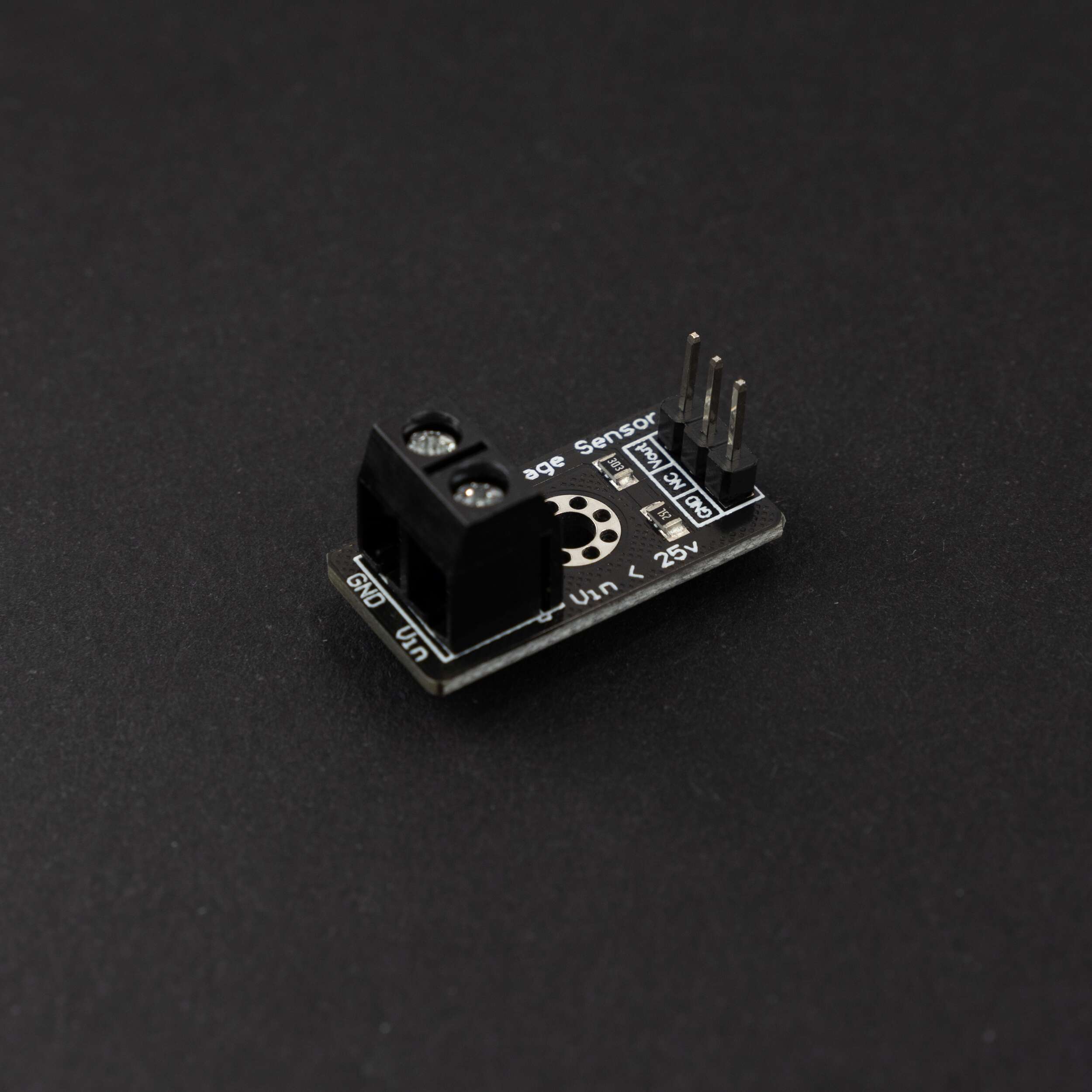
Voltage Sensor Module DC 0-25V – HD Version
EGP 20
See other suppliers →Description
0-25V DC Voltage Sensor Module The voltage sensor module is a small size 0-25 DC voltage sensing device. The design of the module is based on a resistive voltage divider circuit. It is a voltage sensor module that reduces the input voltage signal by a factor of 5 and generates a corresponding analog output voltage concerning step down voltage factor. This voltage measurement circuit is small and portable and can be used to detect under and over-voltage faults in electrical circuits. Voltage Sensor Module Pinout Configuration Pin Name Description Vin The positive terminal of the External voltage source (0-25V) GND The negative terminal of the External voltage source Vout Analog pin connected to Analog pin of Arduino NC Not Connected – Ground Pin connected to GND of Arduino Voltage Detection Sensor Module Features & Specifications Input Voltage: 0 to 25V Voltage Detection Range: 0.02445 to 25 Analog Voltage Resolution: 0.00489V Needs no external components Easy to use with Microcontrollers Small, cheap, and easily available Dimensions: 25 × 13 × 13 mm Brief about Voltage Sensor Module The voltage Detection Sensor Module is a simple and very useful module that uses a potential divider to reduce any input voltage by a factor of 5. This allows us to use the Analog input pin of a microcontroller to monitor voltages higher than it capable of sensing. For example, with a 0V – 5V Analog input range, you can measure a voltage up to 25V. This module also includes convenient screw terminals for easy and secure connections of a wire. The internal circuit diagram of the Voltage Sensor Module is given below. The voltage circuit consists of a voltage divider circuit of two resistors in which R1 is 30K and R2 is 7.5K. How to Use Voltage Sensor Module with Arduino Interfacing a voltage sensor with Arduino or any other microcontroller is pretty straightforward. Connect the V CC and GND of the voltage source whose voltage is to be measured to the screw terminals of the voltage sensor. Connect the S and – (GND) pins of the voltage sensor to the Analog pin and GND of Arduino respectively. Input and output voltage can be calculated using: Vin = Vout * (R2/(R1+R2)) Here R1 = 30K ohm and R2 = 7.5K ohm Vout = (analogvalue * 5 / 1024).
From the supplier's page.
makhzan doesn't sell — every offer opens the supplier's own site.