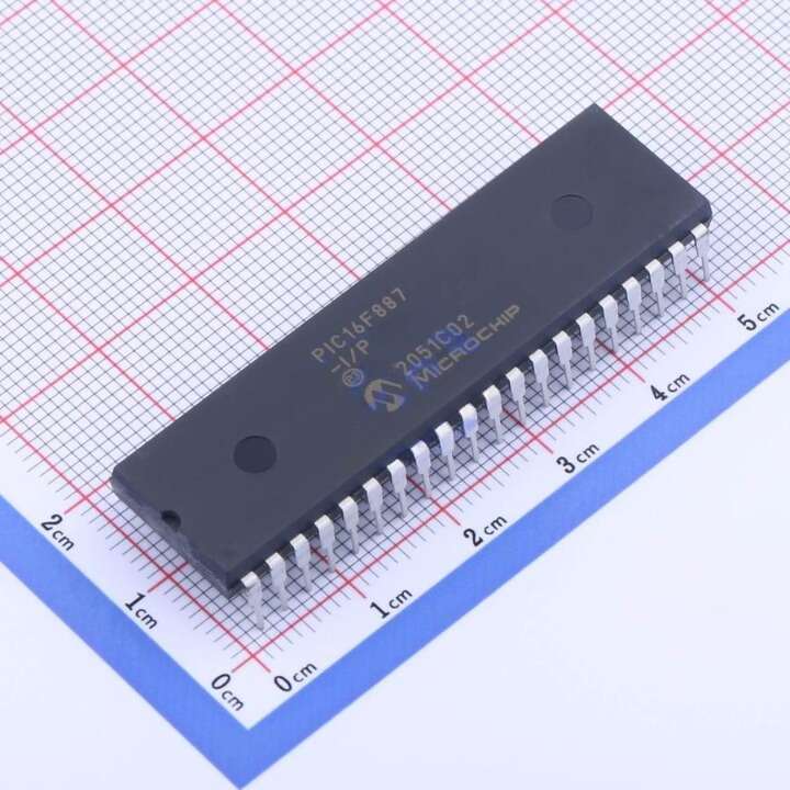
PIC16F887-I/P 20MHz Microcontroller IC PDIP-40
EGP 165
See other suppliers →Description
PIC16F887-I/P 20MHz Microcontroller IC PDIP-40 The PIC16F887 is an 8-bit microcontroller from Microchip. The 40-pin IC has 14 Channel 10-bit ADC making it suitable for applications that require more ADC inputs. The IC also has 2 Comparators, and 2 Timers (8-bit and 16-bit) and supports SPI, I2C, and UART communication protocols. It can operate at a speed of up to 20MHz with an external oscillator and also has a precision internal oscillator tunable between 8MHz to 32kHz. The IC supports nanoWatt technology allowing it to consume very low power and operate in Power-Saving sleep mode. It also has a wide operating voltage from 2V to 5.5V making it suitable for battery-powered applications. The IC also supports safety features like Power-on Reset (POR), Brown-out Reset (BOR), Low Current Watchdog Timer (WDT), etc making it suitable for task-critical and industrial applications. The controller supports In-Circuit Serial Programming (ICSP) allowing the designer to program the controller easily even without removing it from the actual circuit. Features 14 KB (8K × 14) Flash program memory with self-programming capability. 368 bytes of SRAM and 256 bytes of EEPROM for runtime data storage. Up to 20 MHz clock input (5 MIPS execution). 2.0 V to 5.5 V operating voltage range for flexible power designs. 14-channel 10-bit analog-to-digital converter (ADC) for multiple sensor inputs. Two comparators, programmable reference modules, and capacitive touch support (CTMU). Enhanced Capture/Compare/PWM (ECCP) and multiple Timer modules for motor and control tasks. Integrated MSSP for both SPI and I²C, and EUSART for serial communication. Low-power modes (Sleep, Idle) with nanoWatt XLP support for energy-efficient applications. In-Circuit Serial Programming (ICSP) and debugging (ICD) support. PINOUT Pin Number Pin Name Description 1 MCLR/Vpp/RE3 MCLR is used during programming, mostly connected to programmer like PicKit or 3rd pin of PORTE 2 RA0/AN0 Analog pin 0 or 0th pin of PORTA 3 RA1/AN1 Analog pin 1 or 1st pin of PORTA 4 RA2/AN2/Vref- Analog pin 2 or 2nd pin of PORTA 5 RA3/AN3/Vref+ Analog pin 3 or 3rd pin of PORTA 6 RA4/T0CKI/C1out 4th pin of PORTA 7 RA5/AN4/SS/C2out Analog pin 4 or 5th pin of PORTA 8 RE0/RD/AN5 Analog pin 5 or 0th pin of PORTE 9 RE1/WR/AN6 Analog pin 6 or 1st pin of PORTE 10 RE2/CS/AN7 Analog pin 6 or 2nd pin of PORTE 11 Vdd Ground pin of MCU 12 Vss Positive pin of MCU (+5V) 13 RA7/OSC1/CLKI External Oscillator/clock input pin or 7th pin of PORTA 14 RA6/OSC2/CLKO External Oscillator/clock output pin or 6th pin of PORTA 15 RC0/T1OSO/T1CKI 0th pin of PORT C 16 RC1/T1OSI/CCP2 1st pin of POCTC or Timer/PWM pin 17 RC2/CCP1 2nd pin of POCTC or Timer/PWM pin 18 RC3/SCK/SCL 3rd pin of POCTC 19 RD0 0th pin of POCTD 20 RD1 1st pin of POCTD 21 RD2 2nd pin of POCTD 22 RD3 3rd pin of POCTD 23 RC4/SDI/SDA 4th pin of POCTC or Serial Data in pin 24 RC5/SDO 5th pin of POCTC or Serial Data Out pin 25 RC6/Tx/CK 6th pin of POCTC or Transmitter pin of Microcontroller 26 RC7/Rx/DT 7th pin of POCTC or Receiver pin of Microcontroller 27 RD4 4th pin of POCTD 28 RD5/P1B 5th pin of POCTD 29 RD6/P1C 6th pin of POCTD 30 RD7/P1D 7th pin of POCTD 31 Vss Positive pin of MCU (+5V) 32 Vdd Ground pin of MCU 33 RB0/INT 0th pin of POCTB or External Interrupt pin 34 RB1/AN10 Analog pin 10 or 1st pin of POCTB 35 RB2 /AN8 Analog pin 8 or 2nd pin of POCTB 36 RB3/PGM/AN9 Analog pin 9 or 3rd pin of POCTB or connected to programmer 37 RB4/AN11 Analog pin 11 or 4th pin of POCTB 38 RB5/AN13 Analog pin 13 or 5th pin of POCTB 39 RB6/PGC 6th pin of POCTB or connected to programmer 40 RB7/PGD 7th pin of POCTB or connected to programmer most pins are multi-functional. For example, designator RA3/AN3/Vref+/C1IN+ for the fifth pin specifies the following functions: RA3 Port A third digital input/output AN3 Third analog input Vref+ Positive voltage reference C1IN+ Comparator C1positive input This small trick is often used because it makes the microcontroller package more compact without affecting its functionality. These various pin functions cannot be used simultaneously but can be changed at any point during operation. The following tables, refer to the PDIP 40 microcontroller. Specifications PIC16F887 CPU 8-bit PIC Number of Pins 40 Operating Voltage (V) 2 to 5.5 V Number of I/O pins 35 ADC Module 14ch, 10-bit Timer Module 8-bit(2), 16-bit(1) Comparators 2 DAC Module Nil Communication Peripherals UART(1), SPI(1), I2C(1), MSSP(SPI/I2C) External Oscillator Up to 20Mhz Internal Oscillator 8Mhz to 32KHz Program Memory Type Flash Program Memory (KB) 14KB CPU Speed (MIPS) 5 MIPS RAM Bytes 368 Data EEPROM 256 bytes Applications Design requiring many ADC channels Battery Operated Low Power applications Design requiring Multiple I/O interfaces and communications Ideal for more advanced level A/D applications in automotive, industrial, appliances, and consumer applications. Package Contents 1× PIC16F887-I/P 20MHz Microcontroller IC PDIP-40. Documents Datasheet PIC16F887 CAD Files Download
From the supplier's page.
makhzan doesn't sell — every offer opens the supplier's own site.