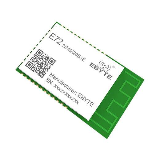
E72-2G4M20S1E CC2652P Wireless ZigBee 3.0 ad hoc network Module 2.4Ghz 20dBm SoC
EGP 950
See other suppliers →Description
Specifications Parameters Hardware parameters parameter value Remark SoC CC2652P1FRGZ Texas Instruments kernel Arm ® Cortex ® -M4F Ultra low power consumption FLASH 352 KB – RAM 80 KB – Crystal frequency 48MHz/32.768KHz External crystal Size 17.5*28.7*2.5 mm width * length * height Antenna form PCB Onboard Antenna Equivalent impedance is about 50 Ω Communication Interface UART 2 -wire serial port, baud rate: 230400 (only supported) Packaging method SMD Stamp half hole, hole spacing 1.27mm Product Weight 1.9±0.1g – Electrical parameters minimum Typical value maximum value unit condition voltage 1.9 3.3 3.8 V More than 3.8V permanently burns the module communicatio n level – 3.3 – V Using 5.0V TTL is recommended to add level conversion Emission current – 106 – mA Instantaneous power consumption @20dBm receive current – 7.3 – mA – sleep current 0.6 μA software shutdown Operating temperature -40 20 85 ℃ – Working humidity 10 60 90 % – Storage -40 20 125 ℃ – RF parameters parameter value Remark Working frequency 2400~2480 MHz Support ISM band transmit power 19.5 dBm Software adjustable blocking power 0 ~ 10.0 dBm The probability of burning at close range is small Receive sensitivity -106 dBm The air rate is 250kbps Modulation GFSK – matched impedance 50 Equivalent impedance of PCB on-board antenna Measured distance 700 m Clear and open, 2.5 meters high, air speed 250kBps Pin Definition pin number pin name Pin Orientation pin usage 1 GND – Ground wire, connected to the power reference ground 2 DIO_7 outpu t STATUS_LED , status indicator, active low. The long light is on standby state, fast blinking means creating a new network or joining a network, 1S periodic blinking means allowing network access; 3 DIO_8 – NC pin, floating; 4 DIO_9 – NC pin, floating; 5 DIO_10 – NC pin, floating; 6 DIO_11 – NC pin, floating; 7 DIO_12 input UART_RX , serial port input signal pin; 8 DIO_13 outpu t UART_TX , serial port output signal pin; 9 DIO_14 – dangling; 10 DIO_15 input BOOT_LOADER , active low; 11、12 GND – Ground wire, connected to the power reference ground; 13 JTAG_TMSC input / output JTAG_TMSC , if not used, please leave it empty; 14 JTAG_TCKC input / output JTAG_TMSC , if not used, please leave it empty; 15 DIO_16 input / output JTAG_TDO , if not used, please leave it empty; 16 DIO_17 input / output JTAG_TDI , if not used, please leave it empty; 17 DIO_18 – NC pin, floating; 18 DIO_19 – NC pin, floating; 19 GND – Ground wire, connected to the power reference ground 20 VCC – The module power supply is positive reference power, the voltage range is 1.9 ~ 3.8V ; 21 DIO_20 – NC pin, floating; 22 DIO_21 – NC pin, floating; 23 GND – Ground wire, connected to the power reference ground; 24 RESET_N enter Reset pin, active low; 25 DIO_22 – NC pin, floating; 26 DIO_23 – NC pin, floating; 27 DIO_24 – NC pin, floating; 28 DIO_25 – NC pin, floating; 39 DIO_26 – NC pin, floating; 30 DIO_27 – NC pin, floating; 31 DIO_28 – NC pin, floating; 32 DIO_29 – NC pin, floating; 33 DIO_30 – NC pin, floating; 34 GND – Ground wire, connected to the power reference ground; File Downloads UserManual_EN Software_Datasheet_EN
From the supplier's page.
makhzan doesn't sell — every offer opens the supplier's own site.