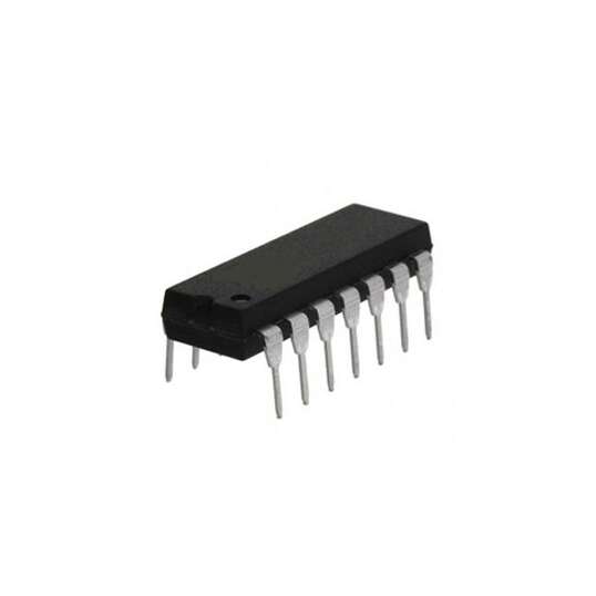
4012 Dual 4-Input NAND Gate 20V PDIP-14
EGP 15
See other suppliers →Description
4012 Dual 4-Input NAND Gate 20V PDIP-14 The 4012 Dual 4-Input NAND Gate is a CMOS logic integrated circuit containing two independent NAND gates, each with four inputs. Packaged in a standard 14-pin PDIP, this IC operates over a wide supply voltage range up to 20 V, offering excellent noise immunity, low quiescent current, and broad compatibility with TTL and CMOS logic families. Each NAND gate performs the Boolean function Y = (A • B • C • D)′ , producing a high output except when all inputs are high. The CD4012’s robust CMOS design makes it suitable for digital logic, control systems, address decoding, and general purpose logic functions in both industrial and hobbyist electronics. Features Four Input OR Gate – Dual Package Typical Operating Voltage: 5V Operating Voltage Range: 3V to 15V Power Dissipation: 500mW Minimum logic Low voltage @+5V: 0.05V Minimum Logic High voltage @+5V: 4.95V Propagation Delay @5V : 50ns (maximum) Available in 14-pin PDIP, GDIP, PDSO packages PINOUT Pin Number Pin Name Description 1 NAND Gate Output pin (1) Output pin of NAND Gate – 1 2,3,4,5 NAND Gate Input pin (1) Four Input pins of NAND Gate -1 7 Ground Connect to the ground of the circuit. 9,10,11,12 NAND Gate Input pin (2) Four Input pins of NAND Gate -2 13 NAND Gate Output pin (2) Output pin of NAND Gate – 2 14 Vcc (Vdd) Used to power the IC. Typically +5V is used Note: Complete Technical Details can be found at the CD4012 datasheet given at the end of this page. Truth Table The output J will follow the logic expression Y= A.B.C.D . This function is also called the Sheffer Stroke Function which is commonly used to form various gate logic using the universal NAND gate logic. Input A Input B Input C Input D Output (Y) 0 0 0 0 1 0 0 0 1 1 0 0 1 0 1 0 0 1 1 1 0 1 0 0 1 0 1 0 1 1 0 1 1 0 1 0 1 1 1 1 1 0 0 0 1 1 0 0 1 1 1 0 1 0 1 1 0 1 1 1 1 1 0 0 1 1 1 0 1 1 1 1 1 0 1 1 1 1 1 0 Specifications Parameter Value Device Type Dual 4-Input NAND gate Logic Family CD4012 Number of Gates 2 Inputs per Gate 4 Package Type PDIP-14 Supply Voltage Range 3 V to 20 V Mounting Type Through-hole Operating Temp Range −55 °C to +125 °C Output Drive CMOS output levels How to use CD4012 IC To use the CD4012 IC, just power it using the Vcc (pin 14) and ground (pin 8) lines. The typical operating voltage of the IC is +5V, but it can also be operated in +5V, +10V and +15V. The output voltage of the IC on the pin Y will be equal to the operating voltage of the IC. As per the truth table shown above, when either one or both the input of the Gate is high the output will be high. The complete working of the gate with a sample circuit is shown in the GIF file below. Applications Logic Buffer circuit Basic Logic Circuits Encoders and Decoders Multiplexers and De-multiplexers Oscillator circuits Networking and Digital Systems Documents Datasheet CD4012BE CAD Files Download
From the supplier's page.
makhzan doesn't sell — every offer opens the supplier's own site.