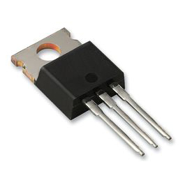
IRF530 N-Channel MOSFET Transistor
EGP 20
See other suppliers →Description
IRF530 is an N-channel MOSFET designed for high-speed and high-power applications. It is compatible to sustain 14 A of continuous current with 100 V voltage. In pulse mode, it can drive a load up to 56 A. In this series, there are other transistors available with slightly different specifications like IRF531, IRF532, and IRF533. The user can operate this MOSFET by the output of ICs and microcontrollers because it is designed to operate with a low gate driving current. This MOSFET can operate in the temperature range of -55˚C to 175 ˚C. It is more popular in industries due to its low cost and ruggedized design. It also features low-on-state resistance and fast switching. For long-life performance, all components use at least 20% below their maximum limit. The maximum operating current of IRF530 is 14 A. Hence, for a better life, it must be operating around 11.2A current and load voltage below 80V. IRF530 Pinout Description Pin No Pin Name Pin Description 1 Gate Control the biasing of MOSFET 2 Drain Current flows-in through Drain 3 Source Current flows-out through Source Features & Specifications Dynamic dv/dt rating Fast switching Ease of paralleling Required simple drive circuit Repetitive avalanche rated Maximum Drain-to-source voltage V DS : 100V Maximum continuous drain current I D : 14A Pulse drain current: 56A Maximum power dissipation: 88W Maximum gate-to-source voltage: ±20V Peak diode recovery dv/dt: 5.5V/ns On-state resistance: 0.16Ω Total gate charge Q g : 26nC Operating junction and storage temperature range: -55˚C to 175˚C Package: TO-220AB Transistor Polarity: N-channel IRF530 Equivalent IRF641, IRF642, IRFB4620, IRFB5620, IRFI530G, IRFS530, BUZ20 Note: More technical specifications can be found in the IRF530 datasheet attached at the end of this page. Switching Characteristics Turn-on delay time t d(on) : 10ns Rise time t r : 34ns Turn-off delay time t d(off) : 23ns Fall time t f : 24ns Working of IRF530 N-channel MOSFET Here we will use IRF530 to run a DC motor. In this circuit diagram, a variable resistance is used to control the speed of the DC motor. A DC motor is connected between the drain and source terminals of IRF530. This simulation is done in proteus. With help of variable resistance, we can set the resistance between gate to drain. The speed of the motor is proportional to the current that passes through the motor (the drain-to-source current or drain current passes through the motor). As the resistance increases, drain current and speed decrease. Similarly, as the resistance decreases, drain current increases and speed also increases. Applications Battery management system and battery chargers Motor drives Solar power supply applications UPS DC-DC and DC-AC Converters Regulators Audio amplifier Solenoid and relay drivers 2D Model and Dimensions If you are designing a PCB or Perf board with this component then the following picture from the IRF530 Datasheet will be useful to know its package type and dimensions. Component Datasheet IRF530 MOSFET Datasheet
From the supplier's page.
makhzan doesn't sell — every offer opens the supplier's own site.