


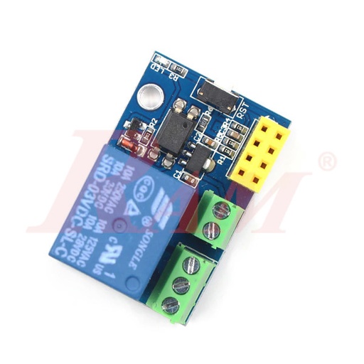


ESP8266 ESP-01 5V WiFi Relay Module
Part number ESP8266
Offers
lowest price firstEach offer shows the shop's own title.
- ESP8266 WIFI Relay Module 5V·checked 15 days agoEGP 60
- ESP8266 ESP-01 5V WiFi Relay Module·Price may be out of date (74 days)EGP 60
- 5V 1-Channel WiFi Relay Board (V2, without ESP8266) – ESP-01 Socket, SPDT·Price may be out of date (74 days)EGP 150
- ESP8266 WiFi 5V 1 Channel Relay Module High Quality·Price may be out of date (74 days)EGP 215
Show 1 out of stock offerHide out of stock offers
- ESP8266 WiFi 1 Relay ModuleRAM ElectronicsOut of stock·checked 14 days agoEGP 65
Details
FromFrom Micro Ohm's description
The ESP8266 ESP-01S Relay Module is a compact and versatile device that combines the power of the ESP8266 WiFi module with a relay, allowing you to create smart home or IoT (Internet of Things) projects that involve controlling electrical appliances or devices remotely. This module is often used to build WiFi-enabled smart sockets, switches, and other automation systems. Here’s a description of its key features and functionalities Features: WiFi Connectivity: Enables remote control and monitoring of devices over a local network or the internet. Relay Switch: Allows you to control electrical appliances or devices with ease. Compact Size: Its small form factor makes it easy to embed in various projects. GPIO Pins: Provides additional pins for interfacing with sensors and peripherals. Serial Communication: Supports communication with other microcontrollers or devices via UART. Easy Programming: This can be programmed using the Arduino IDE or similar development environments. Versatile Applications: Ideal for home automation, IoT projects, energy-saving solutions, and security systems. Specifications: Microproessor: ESP8266 microcontroller with a 32-bit Tensilica L106 RISC CPU Wireless Connectivity: WiFi 802.11 b/g/n (2.4 GHz) for connecting to local networks and the internet. Relay: 250VAC, 10A Single relay switch (Normally Open) for controlling electrical loads GPIO Pins: GPIO0 and GPIO2 are commonly used for relay control and status indication Serial Communication: UART up to 115200 bps Power Supply: 3.3V DC Programming Interface: 4-pin header for programming and firmware flashing. TX and RX pins for serial communication. CH_PD (Chip Enable) and RST (Reset) pins for control Package Includes: 1 x ESP8266 ESP-01S Relay module relay WIFI smart socket
Read moreShow less
From Micro Ohm's description
5V 1-channel WiFi relay board (V2, without ESP8266) ✍️ Introduction A compact 5V 1-channel WiFi relay board (V2) designed to host an ESP-01 module (not included). Add your own ESP-01 to switch lamps, locks, valves, or low-power appliances via Wi-Fi. The board provides a single SPDT relay (COM/NO/NC) , screw terminals for easy wiring, and a simple 5V DC supply input for quick builds and retrofits. 📦 What’s Included 1 × 5V WiFi relay board, V2 (1-channel) — ESP-01 not included ✨ Key Features ESP-01 ready: 2×4 header footprint to plug an ESP-01 (ESP8266) module. Single SPDT relay: common/NO/NC contacts for flexible wiring. 5V supply input: simple power via DC pins or screw terminal (per board). Screw terminals: quick connection for load and supply lines. Compact layout: small footprint for boxes and control panels. DIY-friendly: ideal for Wi-Fi on/off control, timers, and scenes. 📊 Specifications Parameter Value Supply voltage 5 V DC Channels 1 relay Relay output SPDT (COM/NO/NC) Control interface ESP-01 socket (ESP8266) — module not included Terminations Screw terminals for load and supply Indicators Power/Status LEDs (board dependent) Typical use Wi-Fi on/off control via user-programmed ESP-01 Board V2 single-relay form factor 🧰 Compatibility & Tips Program your ESP-01 (e.g., AT firmware, Arduino core, or Tasmota/ESPHome as supported by your workflow). Power the board with a regulated 5 V supply sized for the relay coil and logic. Observe COM/NO/NC wiring; switch the load side , not the logic supply. For AC loads, use a proper enclosure, strain relief, and fusing. Keep RF in mind: mount the ESP-01 with some clearance from metal enclosures. 🎯 Use Cases Wi-Fi control of lamps, LED drivers, and signage power. Door strikes, gate triggers (momentary via firmware), or pumps/fans. Smart scenes with timers/automation via MQTT or Home Assistant (as configured in firmware). Remote reset/power cycling for small devices. 🛡️ Safety & Handling Disconnect power before wiring or moving jumpers. Follow electrical codes when switching mains ; use insulated enclosures. Do not exceed the relay’s printed contact ratings on your board. Provide a fuse appropriate to the load and cable gauge. Keep low-voltage and high-voltage wiring separated and secured. 🚚 Quality, Shipping & Batch Notes Boards are checked for header fit and basic power-on/LED indication. Minor silkscreen or component placement differences can occur between batches. Packed to protect terminals and header pins in transit. ❓ FAQ Q1: Does this include the ESP-01 module? No—this V2 board is without ESP8266 ; add your own ESP-01. Q2: What firmware can I use? Any ESP-01-compatible firmware (e.g., Arduino sketches, AT-based control, or home-automation firmware as your setup supports). Q3: Can it switch AC? Yes—through the relay contacts within the contact ratings printed on your unit. Use proper insulation and fusing. Q4: What power does it need? A regulated 5 V DC supply. Ensure sufficient current for relay actuation. Q5: Can I do momentary vs. toggle actions? Yes—implement in your ESP-01 firmware (GPIO control logic). ✍️ المقدمة لوحة ريليه واي فاي بجهد 5 فولت (قناة واحدة، إصدار V2) مخصّصة لاستيعاب وحدة ESP-01 (غير مرفقة). أضِف وحدتك للتحكم في الإضاءة أو الأقفال أو المضخات عبر شبكة Wi-Fi. توفّر اللوحة ريليه واحدًا SPDT (COM/NO/NC) مع أطراف لولبية للتوصيل السريع وتغذية 5 فولت تيار مستمر من أجل بناءات سريعة وتركيبات مرتّبة. 📦 ما المرفق 1 × لوحة ريليه واي فاي 5 فولت قناة واحدة (V2) — بدون ESP-01 ✨ الميزات الرئيسية جاهزة لـ ESP-01: مقبس 2×4 لتوصيل وحدة ESP-01 (ESP8266). ريليه واحد SPDT: نقاط تلامس COM/NO/NC لخيارات توصيل مرنة. تغذية 5 فولت: طاقة بسيطة عبر دبابيس أو طرف لولبي (حسب اللوحة). أطراف لولبية: توصيل سريع لخطوط الحمل والتغذية. تصميم مدمج: مناسب للصناديق واللوحات الضيقة. ملائم للهواة والمحترفين: للتحكم بالتشغيل/الإيقاف والمهام الزمنية. 📊 المواصفات البند القيمة جهد التشغيل 5 فولت تيار مستمر عدد القنوات 1 ريليه مخرج الريليه SPDT (COM/NO/NC) واجهة التحكم مقبس ESP-01 (ESP8266) — الوحدة غير مرفقة أطراف التوصيل أطراف لولبية للحمل والتغذية المؤشرات لمبات طاقة/حالة (بحسب اللوحة) الاستخدام المعتاد تحكم تشغيل/إيقاف عبر Wi-Fi بوحدة ESP-01 اللوحة إصدار V2 لقناة واحدة 🧰 التوافق والنصائح برمج ESP-01 بما يناسبك (Arduino/AT/Tasmota/ESPHome وفق بيئتك). استخدم مزود 5 فولت منظّمًا بتيار كافٍ لتشغيل الريليه والمنطق. راعِ توصيل COM/NO/NC ؛ قم بالتبديل على جانب الحمل وليس تغذية المنطق. عند أحمال AC، استخدم صندوقًا معزولًا وفيوز وإراحة شد للأسلاك. احفظ مسافة حول وحدة ESP-01 لتحسين استقبال Wi-Fi بعيدًا عن المعدن. 🎯 حالات الاستخدام تحكم Wi-Fi لتغذية لمبات ومحولات LED. أقفال ومشغلات أبواب (نبضي عبر البرنامج). مشاهد ذكية وتوقيت عبر MQTT أو Home Assistant (بحسب البرنامج). إعادة تشغيل/إطفاء أجهزة صغيرة عن بُعد. 🛡️ السلامة والمناولة افصل التغذية قبل التوصيل أو تغيير الجسور. التزم بالمعايير عند التعامل مع التيار المتردد ؛ استخدم عوازل. لا تتجاوز تصنيفات نقاط التلامس المطبوعة على لوحتك. ضع فيوزًا مناسبًا للحمل ومقطع السلك. افصل أسلاك الجهد المنخفض عن أسلاك الجهد العالي وثبّتها جيدًا. 🚚 الجودة والشحن وملاحظات الدُفعات فحص لتركيب المقبس وتشغيل الطاقة/المؤشرات الأساسية. قد تختلف بعض تفاصيل السلك سكرين أو مواضع العناصر بين الدُفعات. تغليف يحمي الأطراف ودبابيس المقبس أثناء الشحن. ❓ الأسئلة الشائعة س1: هل الوحدة تتضمن ESP-01؟ لا—هذه لوحة V2 بدون ESP8266 ؛ أضِف وحدتك الخاصة. س2: ما البرامج المتاحة؟ أي برنامج متوافق مع ESP-01 (سكيتش أردوينو، AT، أو برمجيات أتمتة منزلية حسب بيئتك). س3: هل يمكنها تبديل تيار متردد؟ نعم—عبر نقاط الريليه ضمن التصنيفات المطبوعة على اللوحة. استخدم عزلًا وفيوزًا. س4: ما مصدر الطاقة المطلوب؟ مزود 5 فولت تيار مستمر منظّم بتيار كافٍ لشدّة ملف الريليه والمنطق. س5: هل يمكن جعل التشغيل لحظيًا أو تبادليًا؟ نعم—يُبرمج عبر برمجية ESP-01 (التحكم في مخارج GPIO).
Read moreShow less
From Micro Ohm's description
ESP8266 WiFi 5V 1 Channel Relay Module equip with ESP8266 WiFi module and micro-controllers, through the mobile phone APP to the module to send serial instructions to achieve in the LAN within the relay for wireless control. This onboard 5V, 10A / 250V AC 10A / 30V DC relay, can be continuous pull 10 million times, with diarrhea flow protection and short response time. How to use ESP8266 WiFi 5V 1 Channel Relay Module : Onboard ESP8266 WIFI module has three operating modes: STA (client), AP (hot), STA + AP (client + hot), according to the work of the module to select the corresponding WIFI module mode of operation The The module needs to use the serial debugging software on the computer and USB to TTL module to send AT commands to configure the WIFI module, USB to TTL module RX, TX, GND pin, then the module on the TX, RX, GND pin, IN +, IN – 5V power supply. Note: This product is available in 2 relay module types: JQC3F-5VDC-C and SRD-05VDC-SL-C. It will be shipped randomly. General Info of ESP8266 WiFi 5V 1 Channel Relay Module : Onboard ESP8266 WIFI module, AP mode can be connected at the same time 5 client The module has two ways to work: (i) mobile phone directly mounted on the WIFI module; (ii) mobile phone and WIFI module also carried on the router. Transmission distance: Open environment, the mobile phone mounted on the WIFI module when the maximum transmission distance of 400m. When the WiFI module and mobile phone at the same time carried on the router when the transmission distance according to the router’s signal weakly; Board function description : IN +, IN-: 5V power input; TX, RX, GND: Serial debug pin; Onboard the ESP8266 WIFI module has three work modes: STA (client), AP (hot), the STA + Ap( hot +client), according to the workings of a module to the corresponding choice of WIFI module working mode. Module need before use serial debugging software and USB to TTL module send serial command was carried out on the WIFI module configuration (don’t power outages after configuration is complete, as some of the parameters of WIFI module cannot be saved when the power is cut off), mobile phone and WIFI module after establishing a network connection can use the phone APP control relay. Control Commands : When cell phone equipped with WiFi module sends commands in the following order: (The default baud rate 115200) AT+CWMODE=2, namely AP mode is selected. AT+RST, reset. AT+CIPMUX=1, open multiple connections. AT+CIPSERVER=1,8080, configure the TCP server, set the port. AT+CIOBAUD=9600 set the baud rate to 9600. (working in relays to control the baud rate 9600). AT+CIFSR to view the AP mode IP address, such as the APIP, “192.168.4.1”. Cell phone WIFI signal connection name starts with AI-THINKER or ESP8266. In the “TCP connection” address and port into the APP, such as 192.168.4.1 and 8080. Click on the grey box relays can be controlled. Features : Onboard Module: ESP8266 wifi module; in AP mode it can connect with 5 Clients at the same time Operating Way: cellphone carried on wifi module; cellphone and wifi module carried on the same router, and use the APP to control relay Diode effusion protection; Short response time Package Includes : 1 x ESP8266 WiFi 5V 1-Channel Relay Module Useful Links: IOT Application Transmission Distance(m) 400 Trigger Voltage (VDC) 5 Switching Voltage (VAC) 250@10A Switching Voltage (VDC) 30@10A Baud Rate 9600 Length (mm) 45 Width (mm) 28 Height (mm) 20 Weight (gm) 40 Shipment Weight 0.043 kg Shipment Dimensions 7 × 7 × 3 cm ESP8266 DATASHEET DOWNLOAD ESP8266 INSTRUCTION SET DOWNLOAD DOWNLOAD ZIP FILE DOWNLOAD
Read moreShow less
From Ampere Electronics's description
Product Description The ESP8266 is the name of a micro controller designed by Espressif Systems. The ESP8266 itself is a self-contained WiFi networking solution offering as a bridge from existing micro controller to WiFi and is also capable of running self-contained applications. Interface and sources: IN+, IN-: 5V power input TX, RX: UART communication SWIM, NRST: MCU program interface S1: Mode selection key, default is mode 1 S2: Restore key LED D2 and D4(red): Relay indicator LED D7(red): Mode 1 indicator LED D5(blue): Mode 2 indicator LED D6(green): Working state indicator, the description of D6 as below: (1) It means internal self-configuration or lost connection with the router when D6 off (2) It means the ESP-01 is waiting for the APP configure the password for it when D6 fast blinks every 0.5S (3) It means the whole configuration is done and waiting to establish TCP connection with APP when D6 slow blinks every 2S (4) It means the TCP connection between ESP-01 and APP is OK when D6 is on all the time. Relay control command(must be in hex format): Open the first relay: A0 01 01 A2 Close the first Relay: A0 01 00 A1 Open the second relay: A0 02 01 A3 Close the second Relay: A0 02 00 A2 Package Includes: 1x ESP8266 WIFI Relay Module 5V Relate Products: Sensors | Modules
Read moreShow less
From RAM Electronics's description
ESP8266 Module Not Included
Similar products
 JDY-33 Dual Mode Bluetooth SPP SPP-C Compatible with HC-05/06 slave Bluetooth 3.0 ModuleEGP 1501 shopchecked 14 days ago
 RF Wireless Remote Control 433MHz Long Range 3 Buttons (Up-Down-Stop)EGP 1501 shopchecked 17 days ago
 2.4GHz 5dBi Omni Wi-Fi Booster SMA Male AntennaEGP 1501 shopPrice may be out of date (74 days)
 Bluetooth 4.0 USB Dongle AdapterEGP 1501 shopchecked 20 days ago
 NFC Wristband Rubber Black, 13.56MHz NTAG213 (ISO/IEC 14443 Type A)EGP 1502 shopschecked 16 days ago
 WiFi ESP8266-12-E Serial TTL ModuleEGP 1501 shopchecked 20 days ago
 2.4GHz 5dBi Omni Wi-Fi Booster SMA Female AntennaEGP 1501 shopPrice may be out of date (74 days)
 RF Wireless Remote Control 433MHz Long Range 2 Buttons (ON-OFF)EGP 1501 shopchecked 18 days ago