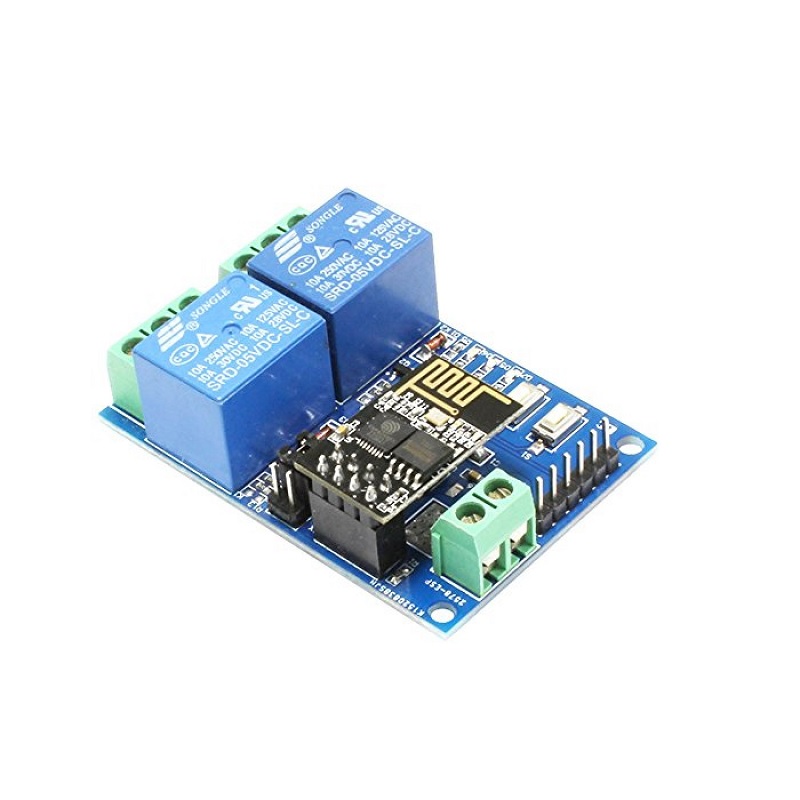
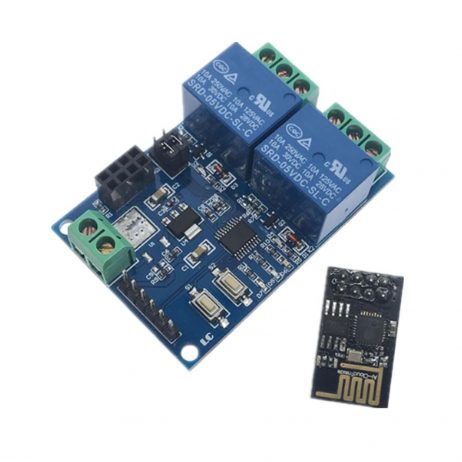


ESP8266 ESP-01 5V 2 Channels WiFi Relay Module Things Smart Home Remote Control Switch
Part number ESP8266
Offers
lowest price firstEach offer shows the shop's own title.
- ESP8266 ESP-01 5V 2 Channels WiFi Relay Module Things Smart Home Remote Control Switch·Price may be out of date (74 days)EGP 325
- ESP8266 ESP-01 5V 4-Channels WiFi Relay Module for Home Remote Control Switch·Price may be out of date (74 days)EGP 430
- ESP8266 ESP‑01 12V 1‑Channel Wi‑Fi Relay Module (Dual Button) Smart Home Remote Control·Price may be out of date (74 days)EGP 450
- ESP8266 ESP‑01 12V 2‑Channel Wi‑Fi Relay Module (Dual Buttons)·Price may be out of date (74 days)EGP 600
Details
FromFrom Micro Ohm's description
ESP8266 ESP-01 5V 2 Channels WiFi Relay Module This WiFi relay module carries an ESP8266 WiFi module and microcontroller. It will send the serial port instructions to the cell phone APP and Implementation within the local area network (LAN) for wireless control relay. This module is ideally suited to controlling larger voltages in your project through WIFI. This is a 1 channel relay module that can be used to activate up to 250V AC and 30V DC. This allows you to build in device control, operating remote lights, or triggering systems when the module is supplied with a signal from an ESP8266 module. The module has an LED that lights relative to the state of the module. A red power activation LED that lights when a signal is received on the IN pin. When a signal is received an audible click can be heard as the relay triggers, connecting the output pins. The relay is controlled via the included ESP8266. This will require configuration via UART prior to full operation. Once it is programmed and powered it will look after itself, making it ideal for use in internet of things “IOT” based projects. How to Use of ESP8266 ESP-01 5V 2 Channels WiFi Relay Module : 5V/1A power adapter and APP “ESP Touch–Demo” Step 1: The 5V/1A power adapter, the positive and negative poles of the power are connected to IN+ and IN- of the module respectively. Step 2: Android mobile terminal installation APP”Esp Touch–Demo”, for the first use of work mode 2 to ESP-01 module configuration WiFi account number and password. Step 3: Android mobile terminal to install APP “Easy TCP–20”, TCP transmission tool, used to send relay control instructions. Click on “SWITCH”, and then enter the 2 relay control instructions and names and contents (instruction form HEX) by the gray blocks in the interface. Features: Transmission distance: In an open environment, the maximum stable transmission distance is 100M when the mobile phone is mounted on the WiFi module. When the WiFi module and mobile phone are carried on the router at the same time, the transmission distance depends on the signal strength of the router. The use of Smart config technology in the mobile phone on the APP ESP-01 WiFi module to complete the account and password configuration, configured username, and password memory function. Onboard 5V, 10A//250V AC 10A//30V DC relay, which can be continuously pulled for 100 thousand times, has diode discharge protection, short response time. Board mode selection and real-time working status indicator. Reserved UART debug interface and STM8 SWIM program download interface. Specifications: Transmission Distance(m) :400 Relay Channel:2 Trigger Voltage (VDC): 5 Switching Voltage (VAC):250@10A Switching Voltage (VDC):30@10A Baud Rate:9600 Package Includes: 1 x ESP8266 ESP-01 12V 1 Channel WiFi Relay Module Things Smart Home Remote Control Switch
Read moreShow less
From Micro Ohm's description
ESP8266 ESP-01 5V 4-Channels WiFi Relay Module for Home Remote Control Switch ESP8266 ESP-01 5V 4-Channels WiFi Relay Module for Home Remote Control Switch is 4 channel WIFI relay module carrying an ESP8266 WIFI module and mature 8 bit MCU, with a Professional switching power supply circuit.It could control the relay by Android phone APP within the local area network (LAN). It is easy to set up. ESP8266 ESP-01 5V 4-Channels WiFi Relay Module for Home Remote Control Switch Features: Integrated design. APP remote control. DC 5V work power supply. Onboard high-quality MCU and ESP8266 WIFI module. Support Two Work Mode: Mode 1:cellphone carry on WIFI module directly. Mode 2: Cellphone and WIFI modules carry on router together. Additional features: USB Relay Module(Without ESP8266). Transmission distance: In the open environment, when the mobile phone is carrying on the WIFI module, the maximum transmission distance is 100 meters. When the WIFI module and cell phone carrier on the router at the same time the signal transmission distance depends on the router signal. 7. Use the Smartconfig technology to complete the configuration of the account and password of the ESP8266 WIFI module on the mobile APP. The configured account and password will be memorized after power off. Optocoupler isolated output, safe and reliable. The board contains 220V,10A/250V AC 10A/30V DC Songle original relay, which can continuously absorb 100,000 times, with the protection of diode current and short response time. PCB material and manufacturing process meets the standards of RoHS. Onboard relay LED indicator, mode option and working statue LED indicator. Reserved UART debug interface and MCU download port for the program. Package Includes: 1 x ESP8266 ESP-01 5V 4-Channels WiFi Relay Module for Home Remote Control Switch Model Type WiFi Relay Module No. of Channels: 4 Operating Voltage (VDC) 5 Operating Temperature (°C) 40℃~85℃ Operating Humidity(%) 0%~95% Length (mm): 60 Width (mm): 63 Height (mm): 20 Weight (g): 19 Shipping Weight 0.02 kg Shipping Dimensions 7 × 6 × 3 cm Datasheet: DOWNLOAD
Read moreShow less
From Micro Ohm's description
ESP8266 ESP‑01 12V 1‑Channel Wi‑Fi Relay Module (Dual Button) | وحدة تتابع واي فاي 12 فولت قناة واحدة (زِران) Overview | نظرة عامة ✅ English This 12V single‑channel Wi‑Fi Relay Module combines an ESP‑01 (ESP8266) Wi‑Fi module with an STM8S103 microcontroller to deliver reliable wireless control of a 10A relay for smart‑home and workshop automation. The board exposes two operating modes (AP/direct and STA/router), two push buttons (S1 Mode switch, S2 Factory reset), rich LED indicators (status, mode, relay state), and screw terminals for safe mains/low‑voltage switching (COM/NO/NC). For developers, it retains UART (TX/RX) for ESP‑01 debugging and SWIM/NRST pads for STM8 programming. In open space the direct AP link reaches up to ~100 m , while router mode depends on the access‑point signal. The relay is the well‑known SRD‑12VDC‑SL‑C (10A@250VAC / 10A@30VDC) . Android phones are supported for SmartConfig provisioning. When the ESP‑01 is unplugged, the board can act as a USB/TTL‑driven relay via the MCU (as a local/bench relay). ✅ العربية تجمع هذه الوحدة ذات القناة الواحدة بجهد 12 فولت بين وحدة ESP‑01 (ESP8266) للاتصال اللاسلكي ومعالج STM8S103 لتوفير تحكم موثوق في ريلاي 10 أمبير لأتمتة المنزل والورشة. تتضمن اللوحة وضعين للتشغيل (وضع نقطة الوصول المباشر AP، ووضع الراوتر STA)، و زرّين (S1 لتبديل الوضع، S2 لإرجاع المصنع)، ومجموعة لمبات بيان (حالة التشغيل، وضع العمل، حالة الريلاي)، و أطراف لولبية آمنة للتوصيل (COM/NO/NC). للمطورين، تتوافر واجهة UART (TX/RX) لتصحيح ESP‑01 ووسادات SWIM/NRST لبرمجة STM8. في بيئة مفتوحة قد يصل مدى الربط المباشر إلى ~100 متر ، بينما يعتمد وضع الراوتر على قوة إشارة نقطة الوصول. الريلاي المستخدم هو SRD‑12VDC‑SL‑C الشائع (10A عند 250VAC أو 30VDC). يدعم إعداد الشبكة عبر Android/SmartConfig . وعند نزع ESP‑01 يمكن استخدام اللوحة كريلاي USB/TTL عبر المتحكم. Key Features | المزايا الرئيسية ✅ English 📶 ESP8266 Wi‑Fi + STM8 MCU : mature 8‑bit control plus popular Wi‑Fi stack. 🔌 10A Relay (SRD‑12VDC‑SL‑C) : switch AC loads up to 250VAC/10A or DC up to 30V/10A. 🗂️ Two Modes : Mode 1 (AP/Direct) phone → ESP‑01; Mode 2 (STA/Router) phone ↔ router ↔ module. 🧭 Dual Buttons : S1 mode selector; S2 factory reset/clear Wi‑Fi. 💡 LEDs : D7 red (Mode 1), D5 blue (Mode 2), D6 green (status), D2/D4 red (relay ON). 🛡️ Protection : two‑pole effusion/optocoupler‑style isolation path, fast switching. 🧪 Developer Friendly : UART TX/RX headers, STM8 SWIM/NRST pads, jumper caps to re‑route ESP‑01 UART. 🔁 Hex Commands (local UART): A0 01 01 A2 → relay ON; A0 01 00 A1 → relay OFF. 🔋 12V Input : wide support for panel supplies (screw terminal IN+ / IN‑ ). ✅ العربية 📶 واي فاي ESP8266 + متحكّم STM8 : تحكم 8‑بت ناضج مع ركيزة الواي فاي الشهيرة. 🔌 ريلاي 10 أمبير (SRD‑12VDC‑SL‑C) : تبديل أحمال حتى 250VAC/10A أو 30VDC/10A. 🗂️ وضعان للتشغيل : الوضع 1 (AP مباشر) الهاتف ↔ ESP‑01؛ الوضع 2 (STA عبر الراوتر) الهاتف ↔ الراوتر ↔ الوحدة. 🧭 زِران : S1 لتبديل الوضع؛ S2 لإرجاع المصنع ومسح إعدادات الواي فاي. 💡 LED : الأحمر D7 لوضع 1، الأزرق D5 لوضع 2، الأخضر D6 لحالة الاتصال، الأحمر D2/D4 لتشغيل الريلاي. 🛡️ حماية : مسار عزل سريع الاستجابة، ومكوّنات حماية ثنائية القطب. 🧪 صديق للمطور : دبابيس TX/RX ، نقاط SWIM/NRST ، وجمبرز لإعادة توجيه UART. 🔁 أوامر هيكس عبر UART: A0 01 01 A2 تشغيل الريلاي؛ A0 01 00 A1 إيقافه. 🔋 دخل 12 فولت : عبر IN+/IN‑ بترمينال لولبي. Board Tour (Callouts) | جولة على اللوحة (المعالم) ✅ English IN+, IN‑ — 12V DC supply input (observe polarity). ESP‑01 socket — pluggable Wi‑Fi module (2×4 header). S1 Button — Mode toggle (defaults to Mode 1/AP ). S2 Button — Factory reset (clears Wi‑Fi credentials and states). Jumper caps — set RX↔RX1 and TX↔TX1 for normal use; move to top to debug ESP‑01 via external USB‑to‑TTL. Relay terminals — COM , NO , NC on the three‑pole terminal. LEDs — D2/D4 red (relay active), D7 red (Mode 1), D5 blue (Mode 2), D6 green (status heartbeat/state). UART pads — TX, RX break‑outs for ESP debug/commands. STM8 SWIM/NRST — programming interface pads. ✅ العربية IN+ وIN‑ — مدخل التغذية 12V DC (انتبه للقطبية). مقبس ESP‑01 — وحدة واي فاي قابلة للفك (هيدر 2×4). الزر S1 — تبديل الأوضاع (الافتراضي الوضع 1/AP ). الزر S2 — إعادة ضبط المصنع (يمسح بيانات الشبكة والحالات). الجمبرز — في الوضع الطبيعي RX مع RX1 و TX مع TX1 ؛ انقل للأعلى لتصحيح ESP‑01 عبر USB‑TTL خارجي. أطراف الريلاي — COM , NO , NC على طرف ثلاثي. LED — D2/D4 أحمر (نشاط الريلاي)، D7 أحمر (وضع 1)، D5 أزرق (وضع 2)، D6 أخضر (إشارة الحالة/القلب). نقاط UART — TX, RX لكشف أخطاء ESP وإرسال الأوامر. SWIM/NRST STM8 — نقاط برمجة المتحكّم. Operating Modes | أوضاع التشغيل ✅ English Mode 1 – Direct (AP) Phone connects directly to the ESP‑01 AP (module acts as hotspot). In open areas, stable range can reach ~100 m . Ideal for bench tests, point‑to‑point control, or when there is no router. Mode 2 – Router (STA) Both phone and module join the same Wi‑Fi router/AP. Range and stability depend on router signal and environment. Allows LAN control and easier multi‑device setups. ✅ العربية الوضع 1 — مباشر (نقطة وصول AP) يتصل الهاتف مباشرة بنقطة الوصول التي ينشئها ESP‑01. في المناطق المفتوحة قد يصل المدى المستقر إلى ~100 متر . مناسب للاختبارات أو التحكم المباشر دون راوتر. الوضع 2 — عبر الراوتر (STA) ينضم الهاتف والوحدة إلى نفس الراوتر/نقطة الوصول. يعتمد المدى والثبات على إشارة الراوتر والبيئة. يسهّل التحكم داخل الشبكة المحلية وتعدد الأجهزة. LED Status Map | خريطة مصابيح البيان ✅ English D6 Green (Status) : Off → self‑configuring or lost router link. Blink 0.5s → waiting for APP to SmartConfig Wi‑Fi credentials. Slow blink 2s → credentials stored; waiting to establish TCP link. Solid → TCP connection with phone established. D7 Red → Mode 1 indicator (AP). D5 Blue → Mode 2 indicator (STA). D2/D4 Red → Relay energized (contacts switched). ✅ العربية D6 أخضر (حالة) : مطفأ → الجهاز يُكوّن نفسه أو فقد الاتصال بالراوتر. وميض كل 0.5 ث → انتظار تهيئة SmartConfig من التطبيق. وميض بطيء كل 2 ث → تم حفظ الحساب وكلمة المرور؛ بانتظار إنشاء اتصال TCP مع الهاتف. ثابت → تم إنشاء اتصال TCP مع الهاتف. D7 أحمر → مؤشر الوضع 1 (AP). D5 أزرق → مؤشر الوضع 2 (STA). D2/D4 أحمر → تشغيل الريلاي (تحويل الملامسات). Wiring the Relay (COM/NO/NC) | توصيل الريلاي (COM/NO/NC) ✅ English COM = Common terminal of the relay. NO (Normally Open) = Open when relay is idle; closes to COM when relay turns ON → use for power‑on to activate loads. NC (Normally Closed) = Closed to COM when idle; opens when relay turns ON → use for power‑off to activate scenarios (e.g., fail‑safe). Use appropriately rated wires; for mains AC follow local electrical codes and isolate low‑voltage side. ✅ العربية COM = الطرف المشترك. NO (عادةً مفتوح) = مفتوح بدون تشغيل؛ يغلق مع COM عند تشغيل الريلاي—مناسب لتغذية الحمل عند التفعيل. NC (عادةً مغلق) = مغلق مع COM في وضع السكون؛ ينفتح عند تشغيل الريلاي—مفيد لحالات عكسية/فيل‑سيف. استخدم أسلاكًا ملائمة للتيار والجهد، والتزم بقوانين الكهرباء المحلية وعزل جانب الجهد المنخفض. Power & Terminals | الطاقة والأطراف ✅ English Supply : 12V DC via IN+ / IN‑ screw terminal. Ensure a clean, regulated source ≥ 500 mA to cover relay coil and Wi‑Fi spikes. UART : TX / RX breakout (ESP‑01 serial). Default baud depends on firmware (commonly 115200 or 9600 ); verify by scanning. STM8 Programming : SWIM, NRST pads plus 5V/12V, GND reference pads. ✅ العربية التغذية : 12 فولت تيار مستمر عبر IN+/IN‑ . يفضّل مصدر منظّم بتيار ≥ 500mA لتغطية ملف الريلاي وذروات الواي فاي. التسلسلي : مفاتيح TX/RX (تسلسلي ESP‑01). تعتمد سرعة البود على الفيرموير (شائع 115200 أو 9600 ). برمجة STM8 : وسادات SWIM و NRST مع مراجع 5V/12V وGND . Pairing & SmartConfig (Android) | الربط والتهيئة الذكية (أندرويد) ✅ English Mode selection : Press S1 until the D7 red (Mode 1) or D5 blue (Mode 2) matches your plan. For router integration, choose Mode 2 . Provisioning : Install a SmartConfig‑capable app (e.g., vendor app or ESP‑Touch utility). Ensure the phone is on 2.4GHz Wi‑Fi. Enter SSID/Password and start configuration. The D6 LED behavior transitions: fast blink → slow blink → solid when TCP link completes. Control : Use the app’s ON/OFF buttons or TCP API to switch the relay. Record the module’s IP from the app/router. ✅ العربية اختيار الوضع : اضغط S1 حتى يتوافق D7 الأحمر أو D5 الأزرق مع خطتك. لربط الراوتر اختر الوضع 2 . الإعداد : ثبّت تطبيقًا يدعم SmartConfig (كتطبيق المصنع أو ESP‑Touch) وتأكد من اتصال الهاتف على 2.4GHz . أدخل اسم الشبكة وكلمة المرور وابدأ التهيئة. يتغير سلوك D6 : وميض سريع → وميض بطيء → ثابت عند اكتمال اتصال TCP . التحكم : استخدم أزرار التشغيل/الإيقاف داخل التطبيق أو واجهة TCP ، واحفظ عنوان IP من التطبيق/الراوتر. Local Serial Control (UART) | التحكم المحلي عبر التسلسلي ✅ English Normal use: keep jumpers at the bottom (RX↔RX1, TX↔TX1). To debug with a USB‑to‑TTL adapter, move jumpers to the top to route the ESP‑01 serial out, then connect GND/TX/RX . Commands (hex) : A0 01 01 A2 → Relay ON (energize; NO closes to COM). A0 01 00 A1 → Relay OFF (de‑energize; NO opens). Send raw hex bytes, not ASCII text. Some terminals support a “hex mode”. ✅ العربية في الاستخدام العادي أبقِ الجمبرز في الأسفل (RX مع RX1، TX مع TX1). لتصحيح عبر محوّل USB‑TTL انقل الجمبرز للأعلى لتوجيه تسلسلي ESP‑01 للخارج، ثم وصل GND/TX/RX . الأوامر (هيكس) : A0 01 01 A2 → تشغيل الريلاي (إغلاق NO مع COM). A0 01 00 A1 → إيقاف الريلاي (فتح NO). أرسل بايتات سداسية خام وليس نص ASCII؛ بعض البرامج توفر وضع “Hex”. Example Integrations | أمثلة تكامل ✅ English Home lighting : Wire lamp live through COM→NO , use router mode for whole‑home control. Garage gate trigger : Use NC for fail‑safe logic with momentary pulses sent over TCP. Bench power reset : Route DC bench supply through relay to cycle equipment using a script via UART hex commands. MQTT bridge : Use an ESP app/bridge on your LAN to translate app control into MQTT topics for broader automation stacks. ✅ العربية إضاءة منزلية : مرر خط الطور عبر COM→NO ، واستخدم وضع الراوتر للتحكم في المنزل. بوابة جراج : استعمل NC من أجل منطق آمن مع نبضات لحظية عبر TCP. إعادة تشغيل أجهزة المختبر : مرر تغذية DC عبر الريلاي لإعادة تشغيل معدّاتك بأوامر UART . جسر MQTT : ضع جسرًا داخل الشبكة يحوّل أوامر التطبيق إلى موضوعات MQTT للتكامل مع منظومات الأتمتة. Specifications | المواصفات الفنية Item Spec Wi‑Fi Module ESP‑01 (ESP8266) MCU STM8S103 8‑bit Relay SRD‑12VDC‑SL‑C , 10A @ 250VAC / 30VDC Supply 12V DC (IN+ / IN‑) Modes Mode 1/AP , Mode 2/STA (router) Distance Up to ~100 m open‑air in AP mode Buttons S1 (mode), S2 (factory reset) Indicators D7 red (Mode 1), D5 blue (Mode 2), D6 green (status), D2/D4 red (relay) Interfaces TX/RX UART; SWIM/NRST pads Phone support Android (for SmartConfig) Safety Notes | ملاحظات السلامة ✅ English Mains wiring must be performed by qualified personnel. Provide isolation, strain relief, and a proper enclosure. Keep low‑voltage and high‑voltage traces/wires separated. Add external snubber/fuse as required by your load characteristics. ✅ العربية توصيلات الجهد المتردد يجب أن ينفّذها مختص. احرص على العزل والتثبيت داخل صندوق. افصل مسارات الجهد المنخفض عن المرتفع. أضف فيوز/سنبر خارجي وفق خصائص الحمل. What’s in the Box | محتويات العبوة ✅ English 1× ESP‑01 Wi‑Fi Relay Module (12V, 1‑channel, dual‑button). 2× Jumper caps (installed). ✅ العربية 1× وحدة ريلاي واي فاي ESP‑01 (12 فولت، قناة واحدة، زِران). 2× جمبرز (مركّبة). : LC Technology ESP‑01 Relay, Wemos D1 Mini relay shields, Sonoff Basic R2 (single relay Wi‑Fi), Hi-Link HLK‑SW16 Wi‑Fi relay. : esp8266 wifi relay, 1 channel relay 12v, smartconfig relay, ap sta wifi switch, uart hex relay, sr d‑12vdc‑sl‑c 10a. : Wi‑Fi smart switch, ESP‑01 relay board, IoT relay module, wireless relay controller.
Read moreShow less
From Micro Ohm's description
ESP8266 ESP-01 12V 4 Channels WiFi Relay Module his WiFi relay module carries an ESP8266 WiFi module and microcontroller. It will send the serial port instructions to the cell phone APP and Implementation within the local area network (LAN) for wireless control relay. This module is ideally suited to controlling larger voltages in your project through WIFI. This is a 4 channel relay module that can be used to activate up to 250V AC and 30V DC. This allows you to build in device control, operating remote lights, or triggering systems when the module is supplied with a signal from an ESP8266 module. The module has an LED that lights relative to the state of the module. A red power activation LED that lights when a signal is received on the IN pin. When a signal is received an audible click can be heard as the relay triggers, connecting the output pins. The relay is controlled via the included ESP8266. This will require configuration via UART prior to full operation. Once it is programmed and powered it will look after itself, making it ideal for use in internet of things “IOT” based projects. How to Use: 12V/1A power adapter and APP “ESP Touch–Demo” Step 1: The 12V/1A power adapter, the positive and negative poles of the power are connected to IN+ and IN- of the module respectively. Step 2: Android mobile terminal installation APP”Esp Touch–Demo”, for the first use of work mode 2 to ESP-01 module configuration WiFi account number and password. Step 3: Android mobile terminal to install APP “Easy TCP–20”, TCP transmission tool, used to send relay control instructions. Click on “SWITCH”, and then enter the 2 relay control instructions and names and contents (instruction form HEX) by the gray blocks in the interface. Features of ESP8266 ESP-01 12V 4 Channels WiFi Relay Module : Transmission distance: In an open environment, the maximum stable transmission distance is 100M when the mobile phone is mounted on the WiFi module. When the WiFi module and mobile phone are carried on the router at the same time, the transmission distance depends on the signal strength of the router. The use of Smart config technology in the mobile phone on the APP ESP-01 WiFi module to complete the account and password configuration, configured username, and password memory function. Onboard 12V, 10A//250V AC 10A//30V DC relay, which can be continuously pulled for 100 thousand times, has diode discharge protection, short response time. Board mode selection and real-time working status indicator. Reserved UART debug interface and STM8 SWIM program download interface. Specifications: Transmission Distance(m) :400 Relay Channel:4 Trigger Voltage (VDC): 12 Switching Voltage (VAC):250@10A Switching Voltage (VDC):30@10A Baud Rate:9600 Package Includes: 1 x ESP8266 ESP-01 12V 4, Channels WiFi Relay, Module Things Smart, Home Remote Control, Switch
Read moreShow less
From Micro Ohm's description
ESP8266 ESP‑01 12V 2‑Channel Wi‑Fi Relay Module (Dual Buttons) | وحدة تتابع واي فاي 12 فولت قناتان (زرّان) Overview | نظرة عامة ✅ English The ESP8266 ESP‑01 12V 2‑Channel Wi‑Fi Relay Module combines an ESP‑01 (ESP8266) Wi‑Fi card with a stable STM8S103 MCU to deliver wireless control of two independent 10A relays . It supports two operating modes— Mode 1 (AP/direct) and Mode 2 (STA/router) —with dual buttons ( S1 mode toggle, S2 factory reset), clear LED indicators for mode, status, and each relay, and screw terminals labeled COM1/NO1/NC1 and COM2/NO2/NC2 . For makers and integrators, the board exposes UART TX/RX for ESP debugging and SWIM/NRST pads for the STM8. Typical direct AP range is ~100 m in open air; in router mode range depends on AP signal (some listings quote up to 400 m line‑of‑sight). Each relay is a SRD‑12VDC‑SL‑C rated 10A @ 250VAC or 10A @ 30VDC . ✅ العربية تجمع وحدة ريلاي واي فاي 12 فولت بقناتين ESP‑01 (ESP8266) بين بطاقة الواي فاي ESP‑01 ومتحكّم STM8S103 لتوفير تحكم لاسلكي في ريلايين مستقلين 10A . تدعم وضعين للتشغيل — الوضع 1 (AP مباشر) و الوضع 2 (STA عبر الراوتر) —مع زرّين ( S1 لتبديل الوضع، S2 لإرجاع المصنع)، ومؤشرات LED واضحة لحالة الوضع والاتصال ولكل ريلاي، وأطراف لولبية موسومة COM1/NO1/NC1 و COM2/NO2/NC2 . للمطورين، توفّر اللوحة TX/RX لتصحيح ESP ووسادات SWIM/NRST لبرمجة STM8. يبلغ المدى عادةً ~100 م في الهواء الطلق بوضع AP؛ وفي وضع الراوتر يعتمد على إشارة نقطة الوصول (وتذكر بعض القوائم حدًا أقصى 400 م في خط نظر). كل ريلاي من نوع SRD‑12VDC‑SL‑C بمعدل 10A عند 250VAC أو 30VDC . Key Features | المزايا الرئيسية ✅ English 📶 ESP8266 Wi‑Fi + STM8 MCU for reliable wireless control. 🔌 Dual 10A relays (SRD‑12VDC‑SL‑C) for AC mains or DC loads. 🗂️ Two operating modes : AP/direct and STA/router . 🧭 Two buttons : S1 mode select; S2 factory reset. 💡 LED map : D7 (Mode 1/AP), D5 (Mode 2/STA), D6 (status heartbeat), D2 & D4 (relay ON indicators). 🧪 Developer access : UART TX/RX , SWIM/NRST pads; jumper caps to route serial. 🔁 Hex UART commands for Relay 1 & 2 control. 🔋 12V DC input via IN+ / IN‑ terminal; on‑board 5V regulation for logic. ✅ العربية 📶 واي فاي ESP8266 + متحكّم STM8 لتحكم لاسلكي موثوق. 🔌 ريلايان 10A (SRD‑12VDC‑SL‑C) للأحمال المتناوبة أو المستمرة. 🗂️ وضعان للتشغيل : AP مباشر و STA عبر الراوتر . 🧭 زرّان : S1 لاختيار الوضع؛ S2 لإرجاع المصنع. 💡 خريطة LED : D7 لوضع 1، D5 لوضع 2، D6 حالة، D2 وD4 حالة تشغيل الريلايات. 🧪 وصول المطور : TX/RX ، ووسادات SWIM/NRST ؛ وجمبرز لتوجيه التسلسلي. 🔁 أوامر هيكس UART للتحكم في الريلاي 1 و2 . 🔋 دخل 12V DC عبر IN+/IN‑ مع تنظيم 5V على اللوحة. Board Tour (Callouts) | جولة على اللوحة (المعالم) ✅ English IN+, IN‑ — 12V supply input. ESP‑01 socket — pluggable Wi‑Fi module. S1 — Mode switch (defaults to Mode 1/AP ). S2 — Factory reset (clears Wi‑Fi credentials). LEDs — D7 red (Mode 1), D5 blue (Mode 2), D6 green (status), D2 (Relay1 ON), D4 (Relay2 ON). Relay terminals — COM1/NO1/NC1 (Relay 1), COM2/NO2/NC2 (Relay 2). Headers — 5V , TX/RX , and GND/SWIM/NRST pads. Jumpers — keep RX↔RX1 and TX↔TX1 in bottom position for normal use; move to top to route ESP‑01 UART for external USB‑to‑TTL debugging. ✅ العربية IN+ وIN‑ — دخل تغذية 12 فولت. مقبس ESP‑01 — وحدة واي فاي قابلة للفك. S1 — مفتاح اختيار الوضع (افتراضيًا الوضع 1/AP ). S2 — استعادة ضبط المصنع (مسح بيانات الشبكة). LED — D7 أحمر (وضع 1)، D5 أزرق (وضع 2)، D6 أخضر (حالة)، D2 (ريلاي 1)، D4 (ريلاي 2). أطراف الريلاي — COM1/NO1/NC1 (ريلاي 1)، COM2/NO2/NC2 (ريلاي 2). الهيدرات — 5V و TX/RX ووسادات GND/SWIM/NRST . الجمبرز — في الوضع الطبيعي اجعل RX مع RX1 و TX مع TX1 في الأسفل؛ وانقلها للأعلى لتوجيه تسلسلي ESP‑01 لتصحيح خارجي. Operating Modes | أوضاع التشغيل ✅ English Mode 1 (AP/Direct) — Phone connects directly to the module’s AP; ideal for bench tests or isolated control. Up to ~100 m typical in open space. Mode 2 (STA/Router) — Phone and module join the same router. Range and stability depend on AP signal; some vendors quote up to 400 m LOS . ✅ العربية الوضع 1 (AP مباشر) — يتصل الهاتف مباشرة بنقطة الوصول الخاصة بالوحدة؛ مناسب للاختبارات أو التحكم المعزول. المدى المعتاد ~100 م في مكان مفتوح. الوضع 2 (STA/راوتر) — ينضم الهاتف والوحدة للراوتر نفسه. يعتمد المدى على إشارة الراوتر؛ وتذكر بعض القوائم حتى 400 م بخط نظر. LED Status Map | خريطة مصابيح البيان ✅ English D6 Green (status) : Off → self‑configuring or router lost; Blink 0.5s → waiting for APP SmartConfig ; Slow blink 2s → credentials stored, awaiting TCP link; Solid → TCP link established. D7 Red → Mode 1/AP indicator. D5 Blue → Mode 2/STA indicator. D2 Red → Relay 1 ON; D4 Red → Relay 2 ON. ✅ العربية D6 أخضر (حالة) : مطفأ → إعداد ذاتي أو فقد راوتر؛ وميض 0.5ث → انتظار SmartConfig ؛ وميض 2ث بطيء → تم الحفظ وبانتظار اتصال TCP؛ ثابت → تم الاتصال. D7 أحمر → مؤشر الوضع 1/AP. D5 أزرق → مؤشر الوضع 2/STA. D2 أحمر → ريلاي 1 يعمل؛ D4 أحمر → ريلاي 2 يعمل. Wiring (COM/NO/NC) | التوصيل (COM/NO/NC) ✅ English COM1/NO1/NC1 control Relay 1 ; COM2/NO2/NC2 control Relay 2 . NO closes to COM when the relay turns ON (use for normal activation). NC opens when the relay turns ON (use for fail‑safe logic). Use proper wire gauge, isolation, and enclosures for mains. ✅ العربية COM1/NO1/NC1 لِريلاي 1؛ COM2/NO2/NC2 لِريلاي 2. NO يغلق مع COM عند تشغيل الريلاي (تفعيل طبيعي). NC ينفتح عند التشغيل (منطق آمن). استخدم مقطع سلك مناسبًا وعزلًا وصندوقًا للحماية مع التيار المتردد. Power & Interfaces | الطاقة والواجهات ✅ English Supply : 12V DC on IN+ / IN‑ ; allow ≥ 1A headroom for relay coil and Wi‑Fi peaks. UART : TX/RX for ESP‑01 (typical baud 9600 or 115200 ; verify). STM8 programming : GND, SWIM, NRST pads + 5V reference header. ✅ العربية التغذية : 12 فولت عبر IN+/IN‑ ؛ يُفضَّل سعة ≥ 1A لهوامش الذروة. التسلسلي : TX/RX لوحدة ESP‑01 (سرعة شائعة 9600 أو 115200 ؛ تحقّق). برمجة STM8 : وسادات GND, SWIM, NRST مع مرجع 5V . Pairing & Apps (Android) | الربط والتطبيقات (أندرويد) ✅ English Use ESP‑Touch / SmartConfig app to provision SSID/password in Mode 2 . Phone must be on 2.4 GHz . For manual TCP control, apps like Easy TCP – 20 let you store hex commands as buttons. Status flow: D6 fast blink → slow blink → solid once TCP link is up. ✅ العربية استخدم تطبيق ESP‑Touch / SmartConfig لتهيئة اسم الشبكة وكلمة المرور في الوضع 2 . يجب أن يكون الهاتف على 2.4 غيغاهرتز . للتحكم اليدوي عبر TCP، يتيح تطبيق Easy TCP – 20 حفظ أوامر هيكس كأزرار. تدفّق الحالة: وميض سريع D6 → وميض بطيء → ثابت بعد اكتمال TCP. Local Serial Control (Hex) | التحكم المحلي بالتسلسلي (هيكس) ✅ English Keep jumpers bottom for normal use (ESP‑01 ↔ MCU). Move top to expose ESP‑01 UART to an external USB‑TTL adapter. Relay 1 : A0 01 01 A2 → ON, A0 01 00 A1 → OFF. Relay 2 : A0 02 01 A3 → ON, A0 02 00 A2 → OFF. Send raw hex bytes (not ASCII). Some terminals provide a HEX mode . ✅ العربية اترك الجمبرز بالأسفل للاستخدام العادي. انقلها لأعلى لإخراج تسلسلي ESP‑01 إلى محوّل USB‑TTL. الريلاي 1 : A0 01 01 A2 تشغيل، A0 01 00 A1 إيقاف. الريلاي 2 : A0 02 01 A3 تشغيل، A0 02 00 A2 إيقاف. أرسل بايتات خام بصيغة هيكس؛ وفّر بعض البرمجيات وضع HEX . Example Scenarios | أمثلة استخدام ✅ English Independent control of two light circuits or pump + valve from one compact module. Garage + Garden : Relay 1 triggers gate opener (momentary NO), Relay 2 toggles garden lights. Bench power management : Use UART hex to sequence two DC supplies on/off with delays. ✅ العربية تحكم مستقل في دائرتي إضاءة أو مضخة + صمام بوحدة واحدة مدمجة. جراج + حديقة : ريلاي 1 لتفعيل البوابة (نبضي NO)، ريلاي 2 لتبديل إضاءة الحديقة. إدارة طاقة المختبر : استخدم أوامر UART لتسلسل تشغيل/إيقاف مصدرين مع تأخيرات. Specifications | المواصفات الفنية Item Spec Wi‑Fi Module ESP‑01 (ESP8266) MCU STM8S103 8‑bit Channels 2 independent relays Relay Model SRD‑12VDC‑SL‑C Contact Rating 10A @ 250VAC , 10A @ 30VDC Supply 12V DC (IN+ / IN‑) UART Baud 9600 / 115200 (firmware‑dependent) Modes AP (Mode 1) , STA (Mode 2) Distance ~100 m AP open field (up to 400 m LOS quoted) Indicators D7 red (Mode 1), D5 blue (Mode 2), D6 green (status), D2/D4 red (relays) Buttons S1 mode, S2 reset Interfaces TX/RX , 5V header , GND/SWIM/NRST Shipping dims/weight 7 × 4 × 2 cm , ~0.01 kg (reference) Safety Notes | ملاحظات السلامة ✅ English Mains wiring must be executed by qualified personnel; use proper creepage, fusing, and an insulated enclosure. Keep low‑voltage side isolated from high‑voltage wiring; add snubbers for inductive loads. ✅ العربية تنفيذ أسلاك التيار المتردد يجب أن يقوم به مختص؛ استخدم مسافات عزل وفيوز وصندوقًا عازلًا. افصل جانب الجهد المنخفض عن المرتفع؛ أضف snubber للأحمال الحثية. What’s in the Box | محتويات العبوة ✅ English 1× ESP‑01 12V 2‑Channel Wi‑Fi Relay Module (dual buttons) 2× Jumper caps (installed) ✅ العربية 1× وحدة ريلاي واي فاي قناتان 12 فولت ESP‑01 (زرّان) 2× جمبرز (مركّبة) : LC Tech ESP‑01 2CH, Sonoff Dual R2, HLK‑SW16 dual relay Wi‑Fi. : esp8266 dual relay, wifi smart switch 2 channel 12v, smartconfig esp touch, uart hex relay r1 r2. : 2‑channel Wi‑Fi relay, ESP‑01 dual relay board, IoT dual switch.
Read moreShow less
Similar products
 AHC25A Weekly Digital Time SwitchEGP 5201 shopchecked 21 days ago
 SONOFF MINI R2 – Two Way Smart SwitchEGP 5401 shopchecked 15 days ago
 Power Relay JQX-80F(JQX-59F) 24VDC 80AEGP 5501 shopchecked 25 days ago
 2-Channel 12V RF Wireless Relay Switch (433 MHz)EGP 5501 shopPrice may be out of date (74 days)
 433MHz 12V 2 Channel Relay Module Wireless with RF Remote Control Switch with BatteryEGP 5501 shopPrice may be out of date (74 days)
 Remote Control Switch 4Ch 433Mhz 12Vdc with RemoteEGP 5501 shopchecked 20 days ago
- DFRobot Gesture & Touch Recognition SensorEGP 5501 shopchecked 15 days ago
 Solid State Relay Module 8 Channel – 5VdcEGP 5751 shopchecked 24 days ago