


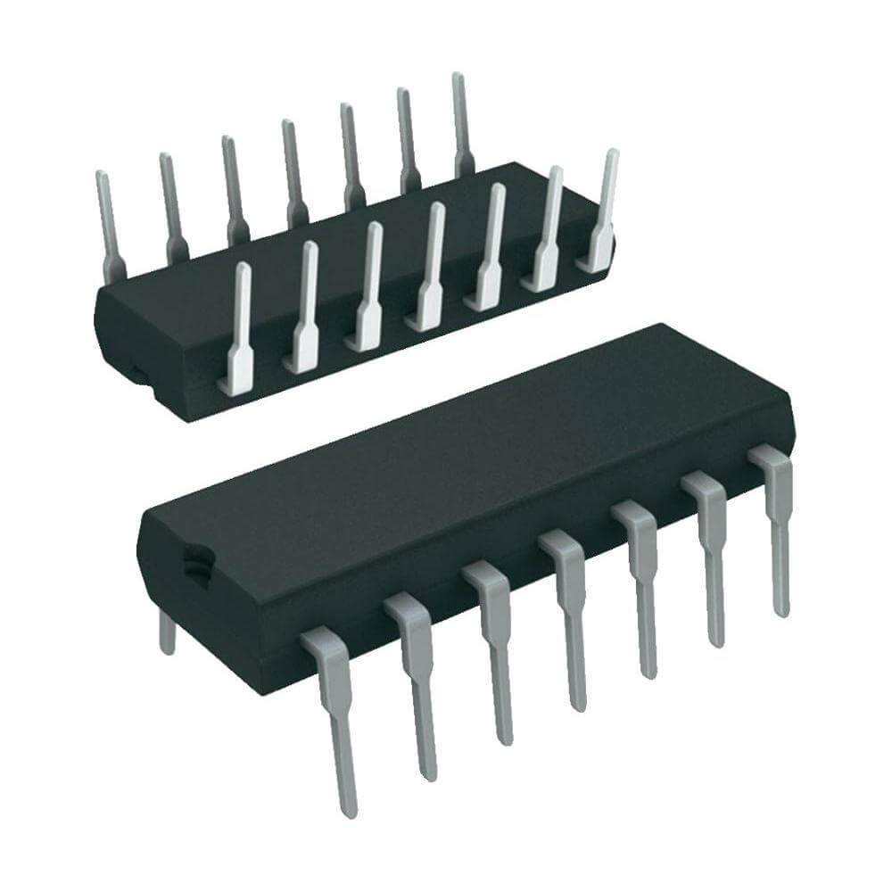
7404 NOT Gate 5V 24mA IC DIP-14
Part number 7404
- Sold by 2 shops · in stock at 2 · EGP 7 – 10
- 8 similar products, from EGP 7
Offers
lowest price firstEach offer shows the shop's own title.
- 7404 NOT Gate 5V 24mA IC DIP-14checked 22 days agoEGP 7
- 7404 Hex Inverter NOT GATE DIP-14Price may be out of date (76 days)EGP 10
What the shops say
From Makers Electronics's listing
Description
7404 NOT Gate 5V 24mA IC DIP-14 The 7404 is a high-speed TTL (Transistor-Transistor Logic) integrated circuit featuring six independent inverters (NOT gates) in a 14-pin Dual In-Line Package (DIP-14). Each gate performs logical inversion: when the input is HIGH, the output is LOW, and vice versa. This IC is widely used in digital electronics for signal inversion, logic-level shifting, and oscillator circuits. Features: Six independent inverters (NOT gates). TTL-compatible logic levels. Wide operating voltage range: 4.75V to 5.25V. Low power consumption per gate. Specifications: Category Integrated Circuits (ICs)/Logic/Gates and Inverters Manufacturer TI Package PDIP-14 Input Logic Level – High 2V Logic Family 74LS Series Input Logic Level – Low 800mV Operating Temperature 0℃~+70℃ Output Logic Level – Low 500mV Output Logic Level – High 2.7V~3.4V Propagation Delay 15ns@5V,15pF Voltage – Supply 4.75V~5.25V Current – Output High (IOH) 400uA Number of Channels 6;1 Current – Output Low (IOL) 8mA Pin Configuration: Foot Print: Explanation of the circuit: When switch is off, input pin of NOT gate will get connected to ground through the pull down resistor. Gate will consider it as logical LOW, So output will be HIGH and LED will turn ON. If the input pin is left unconnected ( not connected to pull down resistor and switch ), IC will assume itself that, voltage at the gate input is logical HIGH. So, turning off the switch without connecting pull down resistor will not give logical LOW at the input. That is, switch will have no effect in changing the voltage level at the gate input if pull down resistor is not connected. Similarly, when the switch turns on, voltage across the input pin will be 5V. Gate will consider it as logical HIGH. so the output will be logical LOW. This will turn off the LED. A current limiting resistor is provided in series with LED to protect LED from overcurrent. Truth table of this circuit is given below. Applications: Signal inversion in digital circuits. Logic-level shifting between different voltage systems. Oscillator circuits for clock generation. Pulse shaping and signal conditioning. Interface between CMOS and TTL logic families. Package Included: 1x 7404 NOT Gate 5V 24mA IC DIP-14. Datasheet: SN74LS04.
Read moreShow less
From Micro Ohm's listing
Description
7404 Hex Inverter NOT GATE DIP-14 7404 IC NOT Gate NOT gate is commonly used to INVERT a logical HIGH to logical LOW or logical LOW to logical HIGH. Each NOT gate has one input and one output. Commonly used NOT gate IC is 7404. Pinout diagram of 7404 is given below. Each 7404 has 6 NOT gates arranged as shown in the following figure. 14th pin is the Vcc and 7th pin is the Ground. Recommended operating conditions of 7404 Recommended operating conditions of 7404 is given in the following table. Supply voltage should be less than 5.25V and greater than 4.75V. A voltage greater than 2V will be considered as HIGH level and voltage less than 0.8V will be considered as LOW level. Truth table of NOT gate Truth table of NOT gate is given below. NOT gate will give a HIGH output, if the input is LOW. Similarly output will be HIGH, if the input is LOW. Control 7404 using Switch Circuit to control 7404 using switch is given below. 5V is supplied from an Arduino board or from 7805 Voltage regulator. Each 7404 has six NOT gates. Any NOT gate can be used in the circuit. First NOT gate is used in this circuit ( A1,Y1 ). Explanation of the circuit When switch is off, input pin of NOT gate will get connected to ground through the pull down resistor. Gate will consider it as logical LOW, So output will be HIGH and LED will turn ON. If the input pin is left unconnected ( not connected to pull down resistor and switch ), IC will assume itself that, voltage at the gate input is logical HIGH. So, turning off the switch without connecting pull down resistor will not give logical LOW at the input. That is, switch will have no effect in changing the voltage level at the gate input if pull down resistor is not connected. Similarly, when the switch turns on, voltage across the input pin will be 5V. Gate will consider it as logical HIGH. so the output will be logical LOW. This will turn off the LED. A current limiting resistor is provided in series with LED to protect LED from overcurrent. Truth table of this circuit is given below. Alternate Method NOT gate can be controlled by another circuit also. Circuit is done as shown in the following diagram. Here pull down resistor is replaced by a switch. Switch is used to control the connection of gate input to ground. When the switch turns on, gate input get connected to ground. Output is connected to an LED through a current limiting resistor for LED protection. Switch in the previous circuit is replaced by a pull up resistor. Pull up resistor pulls the input pins to HIGH, when switch is closed. If pull up resistor is not used, when switch turns on, power supply get shorted through the switch. This will result in large current and will damage the power supply. Explanation of the Circuit When the switch turns off, gate input pin get HIGH voltage from the voltage source through the pull up resistor. So output will be LOW and LED will turn off. But when the switch turns on, gate input get connected to ground and hence the gate input pin will be at logical LOW. So the output will be HIGH. This will turn on LED. Truth table of this circuit is given in the following table. 7404 IC NOT Gate Datasheet
Read moreShow less
Similar products
 LTC4054E Battery Management SMD IC SOT-23-5EGP 71 shopchecked 25 days ago
 LM339 Quad Single Supply Comparator ICEGP 7 – 122 shopsPrice may be out of date (76 days)
 7432 IC Quad 2-Input OR Gate DIP-14EGP 7 – 153 shopschecked 14 days ago
 CD4001 (Quad 2-Input NOR Gate)EGP 7 – 172 shopschecked 18 days ago
 7408 IC Quad 2-Input AND Gate DIP-14EGP 7 – 153 shopschecked 15 days ago
 MSM4008RS IC DIP 16 PinEGP 71 shopchecked 18 days ago
 OB25133JPA SOP-7 AC-DC Controllers and Regulators SMDEGP 71 shopchecked 13 days ago
 4052 (8-channel analog multiplexer/demultiplexer)EGP 71 shopchecked 28 days ago