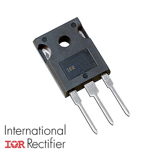
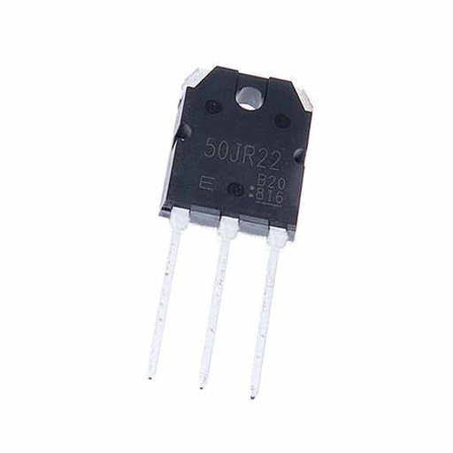
40T120FES Field Stop Trench IGBT Transistor 1200V 40A TO-247
From the shop's description
40T120FES Field Stop Trench IGBT Transistor 1200V 40A TO-247 The 40T120FES is a 1200V Field Stop Trench IGBT with an integrated ultra-soft, fast recovery anti-parallel diode, housed in a TO-247 package. Produced using advanced Field Stop Trench IGBT technology, the device provides low VCE(SAT), high switching performance and excellent quality, and is designed for PFC, UPS and inverter applications. The IGBT blocks 1200V (VCES) and handles a continuous collector current of 80A at TC = 25°C (40A at TC = 100°C), with a pulsed collector current capability of 160A. The low collector-emitter saturation voltage of only 2.0V (typ.) at IC = 40A minimizes conduction losses, while high speed switching (turn-off delay time 308ns typ., fall time 40ns typ. at TC = 25°C) keeps the total switching energy down to just 2.50mJ (typ.). Features 1200V collector-emitter voltage (VCES) High speed switching and low power loss Low saturation voltage: VCE(sat) = 2.0V (typ.) @ IC = 40A 80A continuous collector current @ TC = 25°C (40A @ TC = 100°C), 160A pulsed High input impedance Ultra soft, fast recovery anti-parallel diode: trr = 100ns (typ.) Ultra narrowed VF distribution control Positive temperature coefficient for easy paralleling Short circuit withstand time: 10μs Specifications Parameter Symbol Test Condition Min Typ Max Unit ABSOLUTE MAXIMUM RATINGS Collector-Emitter Voltage V CES – – – 1200 V Gate-Emitter Voltage V GES – – – ±20 V Collector Current I C T C = 25°C – – 80 A Collector Current I C T C = 100°C – – 40 A Pulsed Collector Current I CM Pulse time limited by T Jmax – – 160 A Diode Forward Current I F T C = 100°C – – 40 A Diode Pulsed Current I FM Pulse time limited by T Jmax – – 160 A Power Dissipation P D T C = 25°C – – 357 W Power Dissipation P D T C = 100°C – – 142 W Short Circuit Withstand Time t sc V CE = 600V, V GE = 15V, T C = 150°C – – 10 μs Operating Junction & Storage Temperature Range T J , T stg – -55 to +150 °C THERMAL CHARACTERISTICS Thermal Resistance, Junction-to-Ambient R θJA – – 40 – °C/W Thermal Resistance, Junction-to-Case (IGBT) R θJC – – 0.35 – °C/W Thermal Resistance, Junction-to-Case (Diode) R θJC – – 0.8 – °C/W STATIC CHARACTERISTICS (T C = 25°C unless otherwise specified) Collector-Emitter Breakdown Voltage BV CES I C = 1mA, V GE = 0V 1200 – – V Gate-Emitter Threshold Voltage V GE(th) V CE = V GE , I C = 1mA 4.5 5.5 6.5 V Zero Gate Voltage Collector Current I CES V CE = 1200V, V GE = 0V – – 1 mA Gate-Emitter Leakage Current I GES V GE = 20V, V CE = 0V – – ±250 nA Collector-Emitter Saturation Voltage V CE(sat) I C = 40A, V GE = 15V, T C = 25°C – 2.0 2.4 V Collector-Emitter Saturation Voltage V CE(sat) I C = 40A, V GE = 15V, T C = 150°C – 2.45 – V DYNAMIC CHARACTERISTICS (T C = 25°C) Total Gate Charge Q g V CE = 600V, I C = 40A, V GE = 15V – 341 – nC Gate-Emitter Charge Q ge V CE = 600V, I C = 40A, V GE = 15V – 52 – nC Gate-Collector Charge Q gc V CE = 600V, I C = 40A, V GE = 15V – 126 – nC Input Capacitance C ies V CE = 30V, V GE = 0V, f = 1MHz – 6030 – pF Reverse Transfer Capacitance C res V CE = 30V, V GE = 0V, f = 1MHz – 107 – pF Output Capacitance C oes V CE = 30V, V GE = 0V, f = 1MHz – 206 – pF SWITCHING CHARACTERISTICS (V GE = 15V, V CC = 600V, I C = 40A, R G = 10Ω, Inductive Load) Turn-On Delay Time t d(on) T C = 25°C – 65 – ns Rise Time t r T C = 25°C – 55 – ns Turn-Off Delay Time t d(off) T C = 25°C – 308 – ns Fall Time t f T C = 25°C – 40 – ns Turn-On Switching Energy E on T C = 25°C – 1.96 – mJ Turn-Off Switching Energy E off T C = 25°C – 0.54 – mJ Total Switching Energy E ts T C = 25°C – 2.50 – mJ Turn-On Delay Time t d(on) T C = 150°C – 70 – ns Rise Time t r T C = 150°C – 62 – ns Turn-Off Delay Time t d(off) T C = 150°C – 325 – ns Fall Time t f T C = 150°C – 62 – ns Turn-On Switching Energy E on T C = 150°C – 2.35 – mJ Turn-Off Switching Energy E off T C = 150°C – 1.61 – mJ Total Switching Energy E ts T C = 150°C – 3.96 – mJ DIODE CHARACTERISTICS (T C = 25°C unless otherwise specified) Diode Forward Voltage V F I F = 40A, T C = 25°C – 2.4 3.0 V Diode Forward Voltage V F I F = 40A, T C = 150°C – 2.45 – V Reverse Recovery Time t rr I F = 40A, di/dt = 200A/μs, T C = 25°C – 100 – ns Reverse Recovery Current I rr I F = 40A, di/dt = 200A/μs, T C = 25°C – 7 – A Reverse Recovery Charge Q rr I F = 40A, di/dt = 200A/μs, T C = 25°C – 350 – nC Reverse Recovery Time t rr I F = 40A, di/dt = 200A/μs, T C = 150°C – 180 – ns Reverse Recovery Current I rr I F = 40A, di/dt = 200A/μs, T C = 150°C – 10 – A Reverse Recovery Charge Q rr I F = 40A, di/dt = 200A/μs, T C = 150°C – 900 – nC Applications PFC (Power Factor Correction) UPS (Uninterruptible Power Supplies) Inverters Package Content 1 x 40T120FES Field Stop Trench IGBT Transistor 1200V 40A TO-247 DataSheet 40T120FES
Read moreShow less
Similar products
 FGL40N120AND IGBT Power Transistor 1200V 40A TO-264-3EGP 1301 shopchecked 17 days ago
 BUH1215 Bipolar BJT Transistor NPN 700V 22A 200W TO-3PNEGP 1301 shopchecked 26 days ago
 BUH1015 Bipolar BJT Transistor NPN 700V 18A 160W TO-3PNEGP 1301 shopchecked 26 days ago
 2SK1464 MOSFET Transistor TO-3PFEGP 1251 shopchecked 15 days ago
 H30SR5/IHW30N160R5 IGBT Discrete with Anti-Parallel Diode TO-247 1600V 30AEGP 1251 shopchecked 15 days ago
- IRFP9240 Power P-Channel MOSFETEGP 1251 shopchecked 12 days ago
- GT50JR22EGP 1251 shopchecked 15 days ago
 STD2NK100Z 1KV 1.85A 8.5Ω@10V,900mA 70W N Channel TO-252-2(DPAK) Mosfet TransistorEGP 1251 shopchecked 24 days ago