
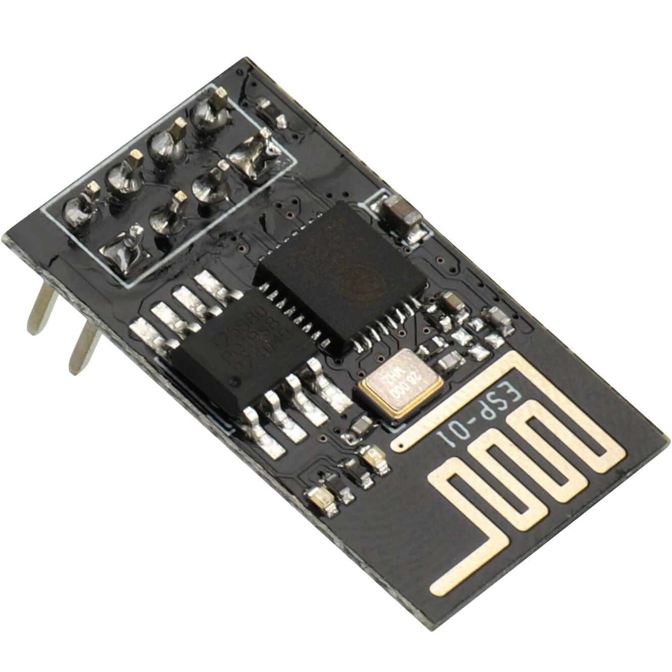
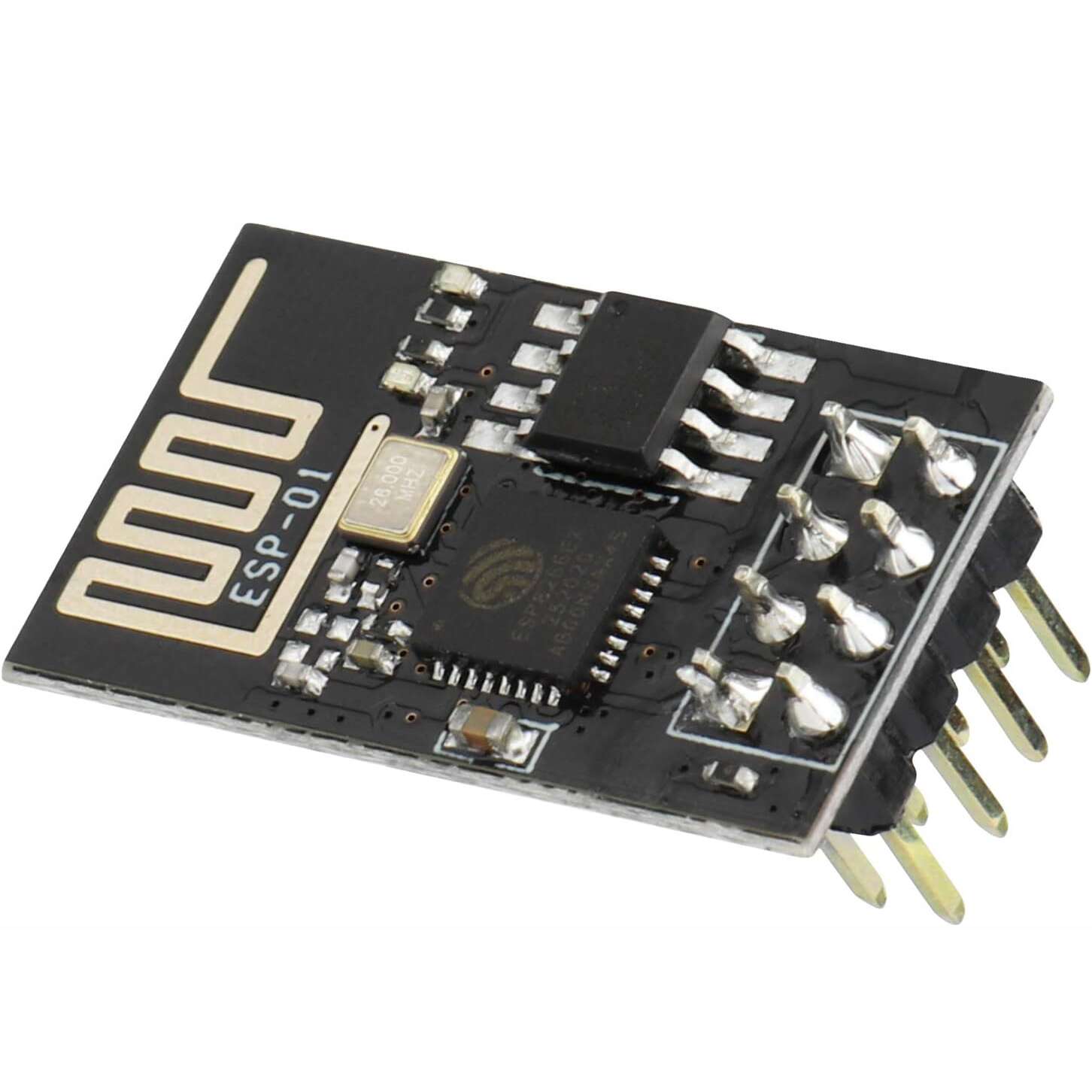



WiFi ESP8266-12-F Serial TTL Module
Part number ESP8266
Offers
lowest price firstEach offer shows the shop's own title.
- WiFi ESP8266-12-F Serial TTL Module·checked 20 days agoEGP 120
- WiFi ESP8266 Serial TTL Module·checked 14 days agoEGP 130
- WiFi ESP8266-12-E Serial TTL Module·checked 20 days agoEGP 150
- WiFi ESP8266-12-S Serial TTL Module·checked 27 days agoEGP 170
Show 4 out of stock offersHide out of stock offers
- WiFi ESP8266-ESP01 Serial TTL ModuleMakers ElectronicsOut of stock·checked 15 days agoEGP 90
- WiFi ESP8266-12-F Serial TTL Module (MAKERS Version)Makers ElectronicsOut of stock·checked 16 days agoEGP 140
- WiFi ESP8266-ESP01S Serial TTL ModuleMakers ElectronicsOut of stock·checked 27 days agoEGP 140
- ESP8266-12E WiFi Serial TTL ModuleRAM ElectronicsOut of stock·checked 14 days agoEGP 195
Details
FromFrom Makers Electronics's description
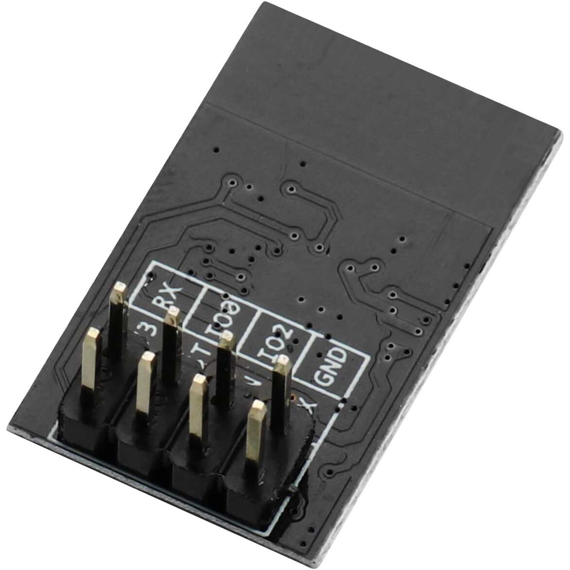
WiFi ESP8266-ESP01 Serial TTL Module The ESP8266 ESP‑01 is a highly compact WiFi module that provides both serial‑to‑WiFi bridging and full standalone microcontroller operation. It employs a 32‑bit Tensilica Xtensa LX106 microprocessor running typically at 80 MHz (and supporting up to ~160 MHz) to deliver built‑in WiFi capabilities and integrated TCP/IP networking functionality. Key Features of ESP8266 ESP-01 WIFI MODULE: 32‑bit Tensilica Xtensa LX106 processor core for onboard computing. WiFi IEEE 802.11 b/g/n connectivity and full TCP/IP stack support. 1 MByte (8 Mbit) external flash memory typical. Two GPIO pins exposed (GPIO0, GPIO2) for peripherals or external signalling. Serial UART interface (TX/RX) for communication or programming. Operates from 3.0‑3.6 V (nominal 3.3 V) power supply. Supports multiple operating modes: Station (STA), Access Point (AP), and combined AP+STA. Specifications: Supply voltage: 3.3 V The working voltage of leads: 3.3 V Current consumption up to 300 mA Supports standard wi-fi – wi-fi 802.11 b, g, n Operates in the 2.4 GHz frequency Supports WPA / WPA2 protection Can work in AP mode (Access Point), STA (standalone) and AP+STA Transmitter power: 19,5 dBm Supports AT commands Has a built-in Flash memory: 1 MB Communication via the serial UART interface Has a built-in PCB antenna Equipped with communication interfaces: SPI, UART, SDIO Has 8 leads pitch of 2 mm 3 x GPIO – digital outputs/inputs Mounting: through the hole – pitch 2,54 (gold pin connectors) Dimensions: 24 x 14 mm Pin Configuration: The module has 8 pins output on the two-row (2×4) gold pin strip raster 2.54 mm. PIN DESCRIPTION Vcc Power supply 3.3 V, current consumption up to 300 mA. GND The mass of the system. Tx The transmitter of the serial interface UART. Rx The receiver of the serial interface UART. RST Reset system – activated by low state. In a mode of regular operation, specify high state 3.3 V. CH_PD Power down – indicating low state causes a transition to sleep mode. For software updates and communication via the UART, you must specify the high state 3.3 V. GPIO0 Lead GPIO number 0. To update software, you must indicate the low status (connect to GND). GPIO2 Lead GPIO number 2. Applications: Add WiFi connectivity (serial‑to‑WiFi bridge) to microcontroller systems such as Arduino or STM32. Use as a standalone WiFi‑enabled microcontroller for IoT nodes, sensor hubs or home automation. Remote telemetry, data logging, wireless sensor networks and embedded control systems. Rapid prototyping of WiFi‑based devices, connecting to cloud or local networks. Educational projects and maker applications requiring low‑cost wireless connectivity. RESOURCES: ESP8266EX Datasheet
Read moreShow less
From Makers Electronics's description
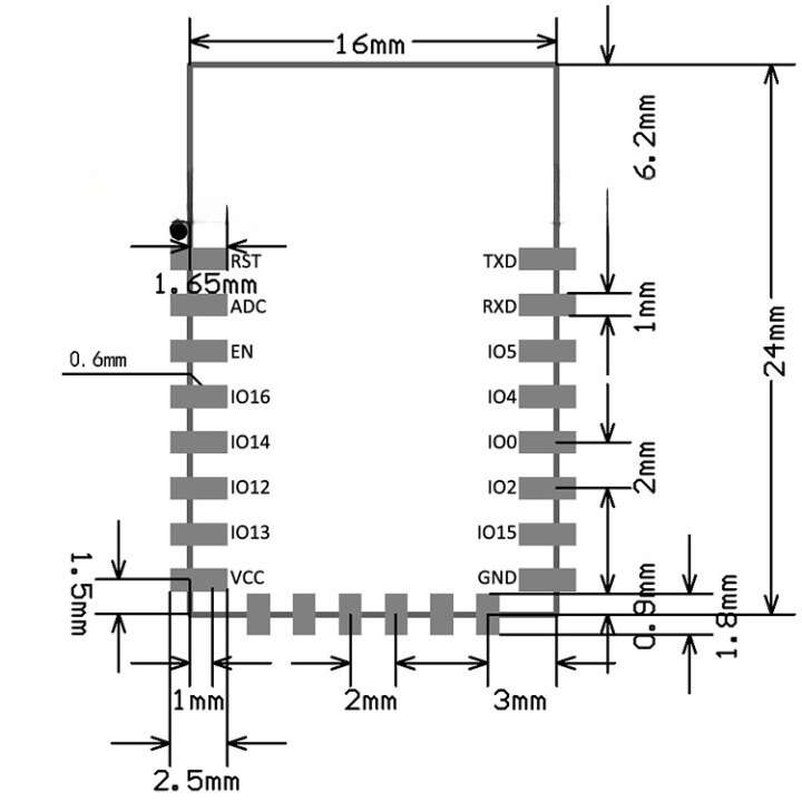
WiFi ESP8266-12-F Serial TTL Module The WiFi ESP8266-12-F Module is a compact, high-performance wireless solution based on the ESP8266 chip, designed for embedded applications requiring reliable WiFi connectivity. Developed by Ai-thinker Team, this module integrates a low-power 32-bit MCU, a complete TCP/IP protocol stack, and advanced RF components, making it ideal for space- and power-constrained designs. With support for 802.11 b/g/n protocols, the ESP-12F offers seamless wireless communication, while its small form factor (16mm x 24mm x 3mm) and ultra-low power consumption (deep sleep mode <10uA) make it perfect for battery-operated devices. It delivers excellent RF performance, including +20dBm output power in 802.11b mode and sensitivity up to -98dBm, ensuring robust connectivity even in challenging environments. The ESP8266-12-F can operate as a standalone application or offload WiFi networking functions from another processor, providing flexibility for a wide range of projects. It also supports over-the-air (OTA) firmware upgrades and features a Smart Link Function for easy setup with Android and iOS devices. Whether you’re building IoT devices, smart home systems, or wireless sensors, the ESP-12F offers the performance, versatility, and ease of use you need. Features : Supports 802.11 b/g/n WiFi standards Integrated low-power 32-bit MCU for standalone operation 10-bit ADC for analog input Complete TCP/IP protocol stack Integrated RF components: TR switch, balun, LNA, power amplifier, and matching network Supports antenna diversity for improved signal reliability Multiple interfaces: SDIO, SPI, UART, I2C, I2S, IRDA, PWM, GPIO Smart Link Function for easy setup with Android and iOS devices OTA firmware upgrade support for convenient updates Low power consumption: deep sleep mode <10uA, standby power <1.0mW (DTIM3) 4MB SPI flash memory for program storage Wide operating temperature range: -40°C to 125°C Certifications: FCC, CE, ROSH Specifications : Parameter Value WiFi Protocols 802.11 b/g/n Frequency Range 2.4GHz – 2.5GHz Operating Voltage 3.0V – 3.6V Operating Current Average 80mA Operating Temperature -40°C to 125°C Package Size 16mm x 24mm x 3mm Flash Memory 4MB Certifications FCC, CE, ROSH Output Power (802.11b) +20dBm Sensitivity (DSSS, 1Mbps) -98dBm Interfaces SDIO, SPI, UART, I2C, I2S, IRDA, PWM, GPIO Security WPA/WPA2, WEP/TKIP/AES Firmware Upgrade UART Download / OTA PIN DESCRIPTION TxD The transmitter of the serial interface UART. RxD The receiver of the serial interface UART. GPIO x Lead GPIO (digital output/ input) with a serial number. GPIO 0 GPIO with special function: To update, you need to indicate the low status (connect to GND). GPIO 15 GPIO No. 15 with a special function: In normal and programming mode should indicate the low status (conect to GND). ADC Input of analog-to-digital converter. REST The system reset. EN (CH_PD) Power down – indication of low state causes a transition to sleep mode.To update, you need to indicate a high status (3.3 V). VCC The Power – 3.3 V. Applications : Internet of Things (IoT) Devices : Enable wireless connectivity in IoT projects. Smart Home Automation : Control lights, appliances, and sensors remotely. Wireless Sensor Networks : Collect and transmit data from environmental sensors. Wearable Electronics : Add WiFi to compact, battery-powered wearables. Embedded Systems : Integrate WiFi into microcontroller-based designs. Remote Control and Monitoring : Build systems for real-time data access. Package Contents: 1x WiFi ESP8266-12-F Serial TTL Module Useful links : Example of connection of ESP-12 Sample Arduino program Comparison of ESP modules The ESP8266 community forum Datasheet : ESP12F-Datasheet
Read moreShow less
From Makers Electronics's description
Description Wi-fi module based on the ESP8266 chip. Works in standard wi-fi 802.11 b/g/n at 2.4 GHz. Equipped with 22 leads – pitch 2 mm, of which 11 is GPIO, 1 ADC and SPI. Has a built-in LED and a PCB antenna. The plate size 24 x 16 mm. The ESP8266 is a low-cost, high-performance wireless SOC that offers countless integration options for WiFi into other systems. Like Arduino, it can handle input and output, but its unique feature is that it includes Wi-Fi. For the majority of “Internet of Things” projects, ESP is the greatest choice when compared to other Wi-Fi options on the market! It can also be included in complex projects because it is so inexpensive—and because of this. And the Arduino IDE is also compatible with ESP. If you’ve used Arduino before, utilizing ESP8266 will be simple for you to learn. IoT projects frequently use Wi-Fi modules from the ESP family. However, there is some misunderstanding across ESP modules as a result of the quick update iteration speed and the absence of module-related information. Differences between ESP12E and ESP12F The “ESP-XX” series includes the ESP-12E. It is a tiny Wi-Fi module that connects a microcontroller or CPU to the wireless network. ESP8266EX serves as the ESP-12E’s brain. Using this module is relatively simple because it doesn’t include any complex circuits or programming. The ESP-12F module belongs to the “ESP-XX” series, which combines a PCB antenna, 4MB of flash memory, and the ESP8266 microprocessor. The 12E has been upgraded into the ESP-12F. With improved stability and a stronger antenna, it is pin compatible. The peripheral circuit, four lamination plate process, greater impedance matching, improved signal output, stability with anti-jamming capabilities, and PCB antenna after expert laboratory testing, flawless matching, and ROHS certification, have all been considerably improved in the ESP8266-12F! Based on the SPI and the new six IO ports, mouth extraction makes programming easier and expands the scope of application. The ESP8266-12F chip’s global remote control feature accepts three commands. The ESP-12F features a ground-breaking design, a redesigned four-layer board, improved RF performance in the revised antenna, and a 30%–50% improvement in communication distance over the ESP-12E! Built-in PCB antenna, 4M bytes Flash, and semi-hole chip technology. The entire IO leads have a metal shielding shell and have received FCC, CE, and RoHS certifications. Note: The only difference between the ESP-12E and ESP-12F is the antenna design; they are the same size and have the same pins. It is claimed that the antenna of the more recent ESP-12F is better optimized. The ESP12F is a newer and more updated version of the ESP12E and features a better antenna design, hence the better output power. Features of the module ESP-12F Features that distinguish the ESP 12-F module on the background of the whole family of ESP-XX: Has 16 pins: 11 x GPIO – digital outputs/inputs 1 x ADC input – analog-to-digital converter 1 x SPI interface 1 x I2C interface 2 x UART (TX, RX) – for communicating, for example with Arduino Mounting: SMD / THT: Holes diameter: 0.9 mm Pitch of leads: 2 mm The default UART communication speed: 115200 bps Equipped with built-in PCB antenna Module shielded Dimensions: 24 x 16 mm Connecting The module has 22 leads, pitch of 2 mm. PIN DESCRIPTION TxD The transmitter of the serial interface UART. RxD The receiver of the serial interface UART. GPIO x Lead GPIO (digital output/ input) with a serial number. GPIO 0 GPIO with special function: To update, you need to indicate the low status (connect to GND). GPIO 15 GPIO No. 15 with a special function: In normal and programming mode should indicate the low status (conect to GND). ADC Input of analog-to-digital converter. REST The system reset. EN (CH_PD) Power down – indication of low state causes a transition to sleep mode.To update, you need to indicate a high status (3.3 V). VCC The Power – 3.3 V. The product is compatible with Arduino Instruction of connecting the module with Arduino basing on the module ESP-01. Tile tolerates a voltage of 3.3 V. Therefore, you must choose Arduino operating on voltage 3.3 V or use a converter. Specifications: Supply voltage: 3.3 V Current consumption at rest: approx. 10 mA Chip: ESP8266 Flash memory: 4 MB Standard: wi-fi 802.11 b/g/n Operates in the 2.4 GHz frequency Supports WPA / WPA2 protections Can work in AP mode (Access Point), STA (standalone) and AP+STA Supports AT commands Communication: UART (Rx, Tx) The default UART speed: 115200 bps Mounting SMD or THT Pitch of leads: 2 mm Hole diameter: 0.9 mm Has 16 pitch leads 2 mm 11 x GPIO – digital outputs/inputs 1 x ADC input – analog-to-digital converter Equipped with communication interfaces: SPI, UART, SDIO Software support Lua Tile sizes: 24 x 16 mm Useful links ESP12F-Datasheet The Wiki-page ESP8266 Example of connection of ESP-12 Sample Arduino program Comparison of ESP modules The ESP8266 community forum
Read moreShow less
From Makers Electronics's description
ESP-01 ESP8266 Serial Wifi Wireless Transceiver Module is an ideal choice for hobbyists to start experimenting with IoT. The dimension of this module is 25mm x 15mm, with simple pin connections (standard 2.4 pin headers), using serial TX/RX to send and receive Ethernet buffers, and similarly, using serial commands to query and change configurations of the WiFi module. ESP8266 ESP-01 Serial WIFI Transceiver Module is a cheap and easy way to connect to internet via WIFI to any microcontroller platforms like Arduino . You can use AT commands to connect to WiFi networks and open TCP/IP connections(without need to have TCP/IP stack running in microcontroller). The module(ESP-01) can work with AT command when used with Arduino,USB to TTL adaptor ( FTDI USB module is recommended). An additional power supply might be needed to power up the board.With GCC too chain and SDK availability opportunities with ESP8266 as a IOT device is endless. Its high degree of on-chip integration allows for minimal external circuitry, including the front-end module, is designed to occupy minimal PCB area. The ESP8266 supports APSD for VoIP applications and Bluetooth co-existence interfaces, it contains a self-calibrated RF allowing it to work under all operating conditions and requires no external RF parts. There is an almost limitless fountain of information available for the ESP8266, all of which has been provided by amazing community support. In the useful links section below you will find many resources to aid you in using the ESP8266, even instructions on how to transforming this module into an IoT (Internet of Things) solution! Specification and Features : Model: ESP-01 S Power: 3.3VDC ( use a 3.3V voltage regulator ! NO level shifter is needed as the IO pins are 5V tolerant) Wi-Fi Direct (P2P), soft-AP Integrated TCP/IP protocol stack It features an integrated TR switch, balun, LNA, power amplifier and matching network Equips integrated PLL, regulators, DCXO and power management units Integrated low power 32-bit CPU could be used as an application processor I/O interfaces: SDIO 1.1/2.0 SPI UART Communication interfaces: STBC 1×1 MIMO 2×1 MIMO A-MPDU & A-MSDU aggregation & 0.4ms guard interval Wake up and transmit packets in < 2ms Standby power consumption of < 1.0mW (DTIM3) Output Power(dBm) : 19.5 Dimensions : 25 (L) x 15 (W) Note: The ESP8266 Module is not capable of 5-3V logic shifting and will require an external Logic Level Converter. Please do not power it directly from your 5V dev board. This new version of the ESP8266 WiFi Module has increased the flash disk size from 512k to 1MB.
Read moreShow less
From Makers Electronics's description
WiFi ESP8266-12-E Serial TTL Module Wi-fi module based on the ESP8266 chip. Works in standard wi-fi 802.11 b/g/n at 2.4 GHz. Equipped with 22 leads – pitch 2 mm, of which 11 is GPIO, 1 ADC and SPI. Has a built-in LED and a PCB antenna. The plate size 24 x 16 mm. Features of the module ESP-12E Features that distinguish the ESP 12-E module on the background of the whole family of ESP-XX: Has 16 pins: 11 x GPIO – digital outputs/inputs 1 x ADC input – analog-to-digital converter 1 x SPI interface 1 x I2C interface 2 x UART (TX, RX) – for communicating, for example with Arduino Mounting: SMD / THT: Holes diameter: 0.9 mm Pitch of leads: 2 mm The default UART communication speed: 115200 bps Equipped with built-in PCB antenna Module shielded Dimensions: 24 x 16 mm Connecting The module has 22 leads, pitch of 2 mm. PIN DESCRIPTION TxD The transmitter of the serial interface UART. RxD The receiver of the serial interface UART. GPIO x Lead GPIO (digital output/ input) with a serial number. GPIO 0 GPIO with special function: To update, you need to indicate the low status (connect to GND). GPIO 15 GPIO No. 15 with a special function: In normal and programming mode should indicate the low status (conect to GND). ADC Input of analog-to-digital converter. REST The system reset. EN (CH_PD) Power down – indication of low state causes a transition to sleep mode.To update, you need to indicate a high status (3.3 V). VCC The Power – 3.3 V. The product is compatible with Arduino Instruction of connecting the module with Arduino basing on the module ESP-01. Tile tolerates a voltage of 3.3 V. Therefore, you must choose Arduino operating on voltage 3.3 V or use a converter. Specifications: Supply voltage: 3.3 V Current consumption at rest: approx. 10 mA Chip: ESP8266 Flash memory: 4 MB Standard: wi-fi 802.11 b/g/n Operates in the 2.4 GHz frequency Supports WPA / WPA2 protections Can work in AP mode (Access Point), STA (standalone) and AP+STA Supports AT commands Communication: UART (Rx, Tx) The default UART speed: 115200 bps Mounting SMD or THT Pitch of leads: 2 mm Hole diameter: 0.9 mm Has 16 pitch leads 2 mm 11 x GPIO – digital outputs/inputs 1 x ADC input – analog-to-digital converter Equipped with communication interfaces: SPI, UART, SDIO Software support Lua Tile sizes: 24 x 16 mm Useful links System documentation ESP8266 The Wiki-page ESP8266 Example of connection of ESP-12 Sample Arduino program Comparison of ESP modules The ESP8266 community forum
Read moreShow less
From Makers Electronics's description
Overview The ESP-12S is a WiFi module based on ESP8266, with built-in 32Mbit Flash, in the small SMD16 package. There’re also onboard PCB antenna and metal shield. In short, it’s a small form factor and fairly high cost effective WiFi module. With the pre-flashed AT firmware, you can control the module through UART AT commands easily. The module integrates MCU inside, supports other developments like Lua/Micropython/Arduino to achieve flexible and fast prototyping, make it easy to integrate the module into IoT applications. Features 802.11b/g/n Wi-Fi SOC Integrated Tensilica L106 ultra-low-power 32-bit micro MCU, run at 80 MHz and 160 MHz frequency, supports RTOS Built-in 1-ch 10 bit high precision ADC Supports UART/GPIO/ADC/PWM/I2C SMD16 package Integrated Wi-Fi MAC/ BB/RF/PA/LNA Supports multi sleep modes, deep sleep current as low as 20uA UART baud rate up to 4Mbps Embedded Lwip protocol stack Supports STA/AP/STA+AP operation mode Supports Smart Config (APP) / AirKiss (WeChat), one key networking Supports UART local firmware upgrade and/or remote firmware upgrade (FOTA) AT commands for getting started fast Supports secondary development, integrated Windows / Linux environment Specification: Module Model ESP-12S WIFI chip ESP8266 Built-in Flash 32Mbit Package SMD16 Antenna Onboard PCB antenna Frequency range 2.4G ~ 2.5G (2400M ~ 2483.5M) WIFI protocol 802.11b/g/n WiFi WIFI mode STA, AP, STA+AP Security WPA / WPA2 Encryption WEP / TKIP / AES Firmware upgrade UART / OTA Transmitting power 802.11b: 16 ±2dBm(@11Mbps) 802.11g: 14 ±2dBm(@54Mbps) 802.11n: 13 ±2dBm(@HT20,MCS7) Receiving sensitivity CCK,1Mbps: -90 dBm CCK,11Mbps: -85 dBm 6Mbps(1/2 BPSK): -88 dBm 54Mbps(3/4 64-QAM): -70 dBm HT20,MCS7(65Mbps, 72.2Mbps): -67 dBm Power Continuous Transmission: ~71mA (peak: 300mA) Model Sleep: ~20mA Light Sleep: ~2mA Deep Sleep: ~20uA IO port 9 UART baudrate 300 ~ 4608000 bps (default 115200bps) Power supply 3.0V ~ 3.6V (current > 500mA) Operating temp. -20 ℃ ~ 85 ℃ Storage condition -40 ℃ ~ 85 ℃, < 90%RH Dimensions 24x16x3 (mm) Pin Definition The ESP-12S module leads to 16 pins Applications The ESP-12S suit for IOT applications such as: Smart home Intelligent building Industrial automation Wearable devices IP camera Intelligent agriculture ESP-12S Datasheet
Read moreShow less
From Future Electronics Egypt's description
This serial Wifi module add wireless ethernet connectivity to your microcontroller / Arduino through serial TTL pins (Rx and Tx). This means that your microcontroller / Arduino can talk to internet (send or recieve wirelessly). Moreover, the module has onboiard microcontroller with its own firmware so it will do all the WiFi related tasks and thus free your main microcontroller / Arduino to do other tasks. The module have many applications starting from sensors network to home automation. Features WiFi communication through serial AT commands. Baud rate: 115200 Operating voltage: 1.7 to 3.6V (3.3V is standard) Integrated low power 32-bit CPU could be used as application processor On board build it antenna. Note: the middle 4 pins (GPIO0, 2, CH_PD, RST) must be pulled high to VCC to enable AT commands. Datasheet and documents . Instructable on how to use with Arduino
Read moreShow less
From RAM Electronics's description
Original AI-Thinker® Brand
Similar products
 SOS Emergency 433Mhz RF Wireless Remote Control ButtonEGP 1201 shopchecked 18 days ago
 2.4G Folded SMA to IPEX Antenna WiFi Bluetooth ZigBee Antenna, 2.5dBi, 2400MHzEGP 1201 shopPrice may be out of date (74 days)
 RFID Reader (125Khz - UART)EGP 1201 shopchecked 16 days ago
 5v 1a wireless power supply charging moduleEGP 1201 shopchecked 24 days ago
 NFC Card – NTAG215 (White PVC)EGP 1201 shopchecked 14 days ago
 Wireless Module (200M Range-433 Mhz)EGP 1201 shopchecked 27 days ago
 JDY-62A 5.0 Bluetooth Stereo ModuleEGP 1251 shopPrice may be out of date (74 days)
 External Adhesive Patch Antenna GSM/GPRS 900-1800MHz with SMA Male Connector – 3M WireEGP 1251 shopchecked 16 days ago