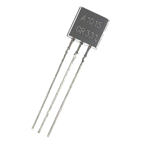
2SA1015 A1015 PNP Transistor
Part number 2SA1015
Price may be out of date. Last checked 74 days ago. Confirm it on the shop's page.
From the shop's description
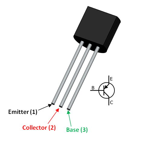
Pin Configuration Pin No. Pin Name Description 1. E Emitter 2. C Collector 3. B Base Features and Technical Specifications Type: p-n-p Power Dissipation: 0.4watts High voltage and High current: Vceo = 50v and Ic = 150mA Low Noise: 1dB Case Material: molded plastic Collector power dissipation: 400mW DC current gain: 400 Collector Emitter and Collector Base breakdown voltage: 50Vdc Base Emitter Saturation Voltage: 1.1Vdc Collector Emitter Saturation Voltage: 0.3Vdc Base Emitter voltage: 1.45Vdc Complementary to 2SC1815 Operating Temperature and Storage Temperature: -55℃ to +150℃ Note: Complete technical details can be found in the A1015 Datashee t linked at the bottom of this page. A1015 Equivalent Transistors NTE290A, 2SA495, 2SA561, 2SA564A, 2SA573, 2SA675, 2SA705, 2SA850, 2SA999, KTA1015, BC212, BC257, BC307, BC557 , 2N3494, 2SA781, KT3108A Where to Use A1015 PNP Transistors? The main use of 2SA1015 is for audio frequency amplifier applications. It can also be used for the switching purpose just like other PNP transistors. When use as an Audio frequency general purpose amplifier, can be operated in the active region. This transistor is further divided into four groups according to the DC current gain, O, Y, G, and L and has 140, 240, 400 and 700 hfe DC current gain respectively. Group DC current gain (hfe) O 140 Y 240 G 400 L 700 Amplification factor usually determined in term of power, for calculating the current gain we use the formula: Gain (hfe) = IC / IB Where, IC is the collector current and IB is the base current of the circuit. How to Use A1015 Transistor? In the below circuit of LED flasher using 2SA1015 , capacitor C1 and R1 used as frequency generator to Q1 transistor which is used as switch for Q2. And, Q2 is used for increasing the current. From capacitor C1 through R2 and LED, Q1 will work until the voltage drop increases across C1. As a result, Q2 starts conducting, and a current flows through LED and it turns ON. While C1 discharged through R1 to a period of time, when C1 discharge out there would be no pressure to bias the base terminal of the Q1. Hence, the Q1 stop working which also stop Q2 to work. Therefore, LED turn OFF and C1 will start again and this cycle continues. And, the turning ON and OFF of LED seems as a flasher. Applications Switching Driver stage amplifier action AF amplifier Can be used Darlington pair Used in making led flasher 2D-Model Component Datasheet A1015 Transistor Datasheet
Read moreShow less
Similar products
 SMD Transistors MMBT3906 2A PNP 200mA 40V 200mW SOT-23EGP 21 shopchecked 21 days ago
 SI2302 A2SHB 20V 2.5A 0.9W 40mΩ@4.5V,2.5A N Channel SOT-23 MOSFET SMDEGP 21 shopchecked 15 days ago
 MMBT3904LT1G 40V 40@0.1mA,1.0V 225mW 200mA NPN SOT-23 Bipolar Transistor SMDEGP 21 shopchecked 13 days ago
 BC517 NPN Darlington Transistor 30V 500mA TO-92EGP 21 shopchecked 19 days ago
- SMD Transistors D882 NPN 3A 30V SOT-89EGP 21 shopchecked 12 days ago
 BC817-40 6C Bipolar NPN Transistors 45V 0.3W 0.5A SOT-23EGP 21 shopchecked 18 days ago
 2N3906 Transistor (40V, 0.2A)EGP 21 shopchecked 13 days ago
 2SC3198 NPN Bipolar Transistors BJT TO-92EGP 21 shopchecked 12 days ago