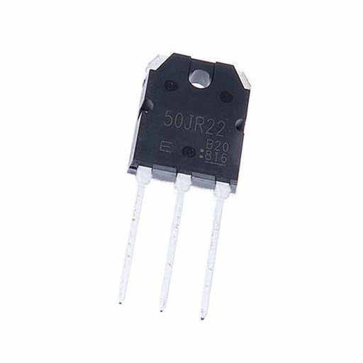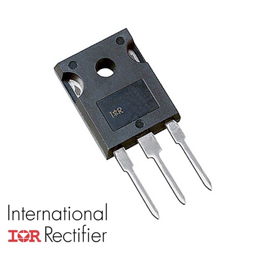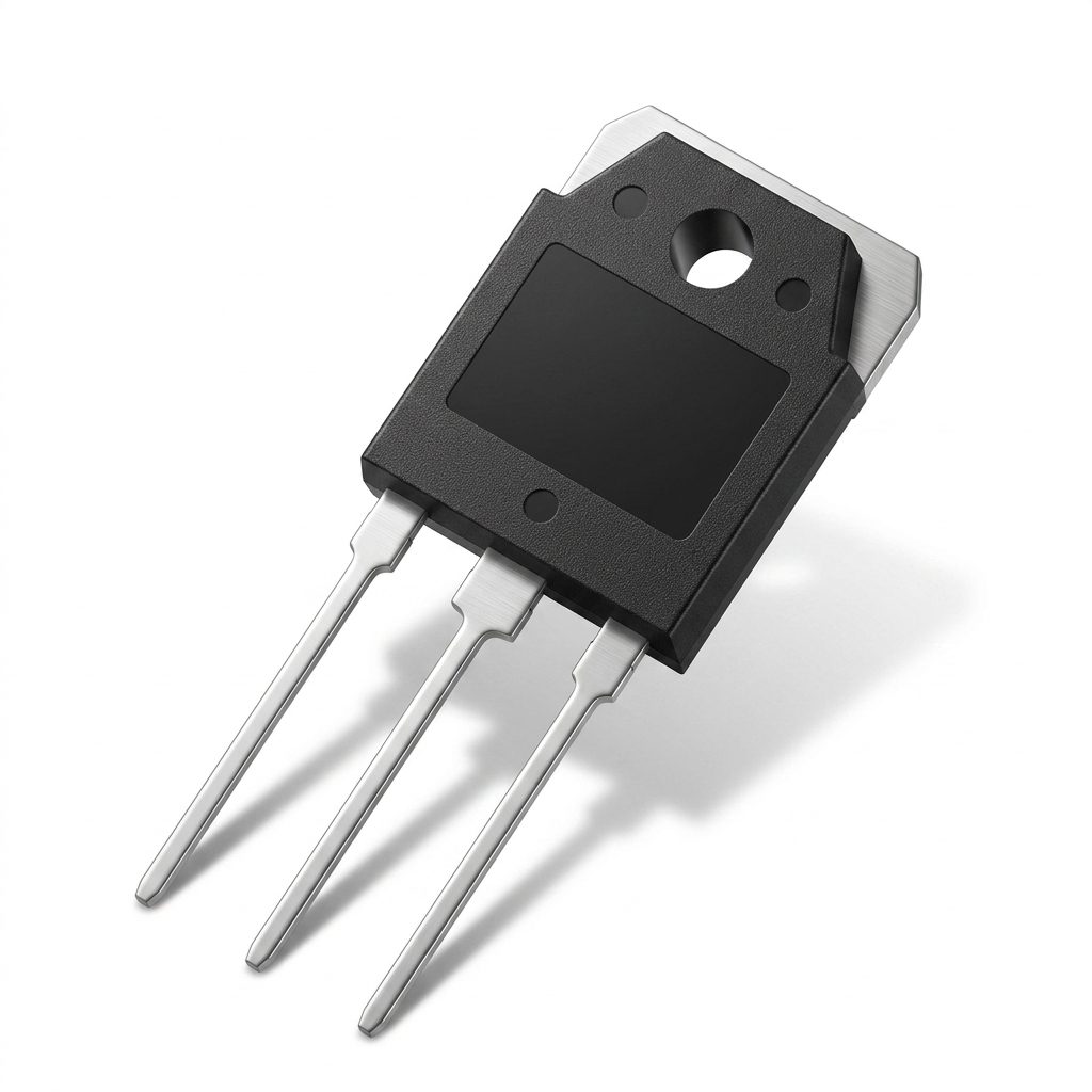
60T65PES High Speed IGBT 650V 100A TO-3P
From the shop's description
60T65PES High Speed IGBT 650V 100A TO-3P The 60T65PES is a High Speed Fieldstop Trench IGBT from MagnaChip Semiconductor, produced using advanced MagnaChip Field Stop Trench IGBT 2nd Generation Technology. This device is designed to provide high efficiency switching behavior together with high ruggedness and excellent quality. It is especially suitable for applications where low conduction losses are essential, including solar inverter, UPS, IH, welder, and PFC applications. The device supports a collector-emitter voltage of 650V and a DC collector current of 100A at TC = 25°C, with a pulsed collector current of 180A limited by maximum junction temperature. The IGBT features low saturation voltage, low switching energy, high input impedance, and a maximum operating junction temperature of 175°C. Its diode section is specified with forward current ratings and reverse recovery characteristics, making it useful in high-speed power conversion circuits. Features High Speed Switching and Low Power Loss VCE(sat) = 1.85V typical at IC = 60A Eoff = 0.53mJ at TC = 25°C High Input Impedance trr = 110ns typical at diF/dt = 500A/µs Maximum Junction Temperature 175°C Short circuit withstand time: 5µs under specified test conditions Low conduction loss for high-efficiency power applications Field Stop Trench IGBT, Second Generation technology Specifications Parameter Value Conditions / Notes Maximum Ratings Collector-Emitter Voltage 650 V VCE DC Collector Current 100 A TC = 25 °C, limited by Tvj max DC Collector Current 60 A TC = 100 °C, limited by Tvj max Pulsed Collector Current 180 A tp limited by Tvj max Turn-Off Safe Operating Area -180 A VCE ≤ 650 V, Tvj ≤ 175 °C Diode Forward Current 60 A TC = 25 °C, limited by Tvj max Diode Forward Current 30 A TC = 100 °C, limited by Tvj max Diode Pulsed Current 200 A tp limited by Tvj max Gate-Emitter Voltage ±20 V VGE Power Dissipation 428 W TC = 25 °C Power Dissipation 214 W TC = 100 °C Short Circuit Withstand Time 5 µs VCC ≤ 400 V, RG = 7 Ω, VGE = 15 V, Tvj = 150 °C Operating Junction Temperature Range -40 to 175 °C Tvj Storage Temperature Range -55 to 150 °C Tstg Soldering Temperature 260 °C Wave soldering, 1.6 mm from case for 10 s Mounting Torque 0.6 Nm maximum M3 screw Thermal Characteristics Thermal Resistance, Junction-to-Ambient 40 °C/W RθJA Thermal Resistance, Junction-to-Case, IGBT 0.35 °C/W RθJC Thermal Resistance, Junction-to-Case, Diode 1.2 °C/W RθJC Static Electrical Characteristics Collector-Emitter Breakdown Voltage Min 650 V IC = 2 mA, VGE = 0 V Collector-Emitter Saturation Voltage Typ 1.85 V, Max 2.4 V IC = 60 A, VGE = 15 V, Tvj = 25 °C Collector-Emitter Saturation Voltage Typ 2.6 V IC = 60 A, VGE = 15 V, Tvj = 175 °C Diode Forward Voltage Typ 1.45 V, Max 2.0 V VGE = 0 V, IF = 25 A, Tvj = 25 °C Diode Forward Voltage Typ 1.35 V VGE = 0 V, IF = 25 A, Tvj = 175 °C Gate-Emitter Threshold Voltage Min 4.0 V, Typ 5.0 V, Max 6.0 V VCE = VGE, IC = 0.5 mA Zero Gate Voltage Collector Current Max 40 µA VCE = 650 V, VGE = 0 V, Tvj = 25 °C Gate-Emitter Leakage Current Max ±100 nA VGE = 20 V, VCE = 0 V Dynamic Characteristics Total Gate Charge Typ 95 nC VCE = 520 V, IC = 60 A, VGE = 15 V Gate-Emitter Charge Typ 19 nC VCE = 520 V, IC = 60 A, VGE = 15 V Gate-Collector Charge Typ 47 nC VCE = 520 V, IC = 60 A, VGE = 15 V Input Capacitance Typ 2327 pF VCE = 25 V, VGE = 0 V, f = 1 MHz Reverse Transfer Capacitance Typ 55 pF VCE = 25 V, VGE = 0 V, f = 1 MHz Output Capacitance Typ 270 pF VCE = 25 V, VGE = 0 V, f = 1 MHz Internal Emitter Inductance Typ 13.0 nH Measured 5 mm from case Switching Characteristics at Tvj = 25 °C Turn-On Delay Time Typ 42 ns VGE = 15 V, VCC = 400 V, IC = 60 A, RG = 7 Ω, Inductive Load Rise Time Typ 54 ns VGE = 15 V, VCC = 400 V, IC = 60 A, RG = 7 Ω, Inductive Load Turn-Off Delay Time Typ 142 ns VGE = 15 V, VCC = 400 V, IC = 60 A, RG = 7 Ω, Inductive Load Fall Time Typ 40 ns VGE = 15 V, VCC = 400 V, IC = 60 A, RG = 7 Ω, Inductive Load Turn-On Switching Energy Typ 0.92 mJ VGE = 15 V, VCC = 400 V, IC = 60 A, RG = 7 Ω, Inductive Load Turn-Off Switching Energy Typ 0.53 mJ VGE = 15 V, VCC = 400 V, IC = 60 A, RG = 7 Ω, Inductive Load Total Switching Energy Typ 1.45 mJ VGE = 15 V, VCC = 400 V, IC = 60 A, RG = 7 Ω, Inductive Load Switching Characteristics at Tvj = 175 °C Turn-On Delay Time Typ 45 ns VGE = 15 V, VCC = 400 V, IC = 60 A, RG = 7 Ω, Inductive Load Rise Time Typ 58 ns VGE = 15 V, VCC = 400 V, IC = 60 A, RG = 7 Ω, Inductive Load Turn-Off Delay Time Typ 152 ns VGE = 15 V, VCC = 400 V, IC = 60 A, RG = 7 Ω, Inductive Load Fall Time Typ 35 ns VGE = 15 V, VCC = 400 V, IC = 60 A, RG = 7 Ω, Inductive Load Turn-On Switching Energy Typ 1.43 mJ VGE = 15 V, VCC = 400 V, IC = 60 A, RG = 7 Ω, Inductive Load Turn-Off Switching Energy Typ 0.53 mJ VGE = 15 V, VCC = 400 V, IC = 60 A, RG = 7 Ω, Inductive Load Total Switching Energy Typ 1.96 mJ VGE = 15 V, VCC = 400 V, IC = 60 A, RG = 7 Ω, Inductive Load Diode Reverse Recovery Characteristics at Tvj = 25 °C Reverse Recovery Time Typ 110 ns IF = 25 A, diF/dt = 500 A/µs Reverse Recovery Current Typ 18 A IF = 25 A, diF/dt = 500 A/µs Reverse Recovery Charge Typ 1.10 µC IF = 25 A, diF/dt = 500 A/µs Diode Reverse Recovery Characteristics at Tvj = 175 °C Reverse Recovery Time Typ 205 ns IF = 25 A, diF/dt = 500 A/µs Reverse Recovery Current Typ 25 A IF = 25 A, diF/dt = 500 A/µs Reverse Recovery Charge Typ 2.67 µC IF = 25 A, diF/dt = 500 A/µs Applications Power Factor Correction (PFC) circuits. Uninterruptible Power Supplies (UPS). Photovoltaic (PV) inverters. Welding equipment. Induction Heating (IH) cookers. DataSheet MBQ60T65PES DataSheet
Read moreShow less
Similar products
 K75EEH5 IGBT Transistor 650V 75A PG-TO247-3EGP 1201 shopchecked 18 days ago
 Power IGBT Transistor G80N60 TO-247 600V 80AEGP 1201 shopchecked 28 days ago
 MLG60T65FUK 60T65 60A 650V TO-247 IGBT transistorEGP 1201 shopchecked 13 days ago
 BUZ50 N-Channel MOSFET Transistor 1000V 2.5A TO-220EGP 1151 shopchecked 16 days ago
- GT50JR22EGP 1251 shopchecked 15 days ago
- IRFP9240 Power P-Channel MOSFETEGP 1251 shopchecked 12 days ago
 H30SR5/IHW30N160R5 IGBT Discrete with Anti-Parallel Diode TO-247 1600V 30AEGP 1251 shopchecked 15 days ago
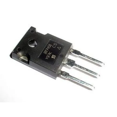 IRFP450 N-Channel MOSFET TransistorEGP 1151 shopPrice may be out of date (74 days)