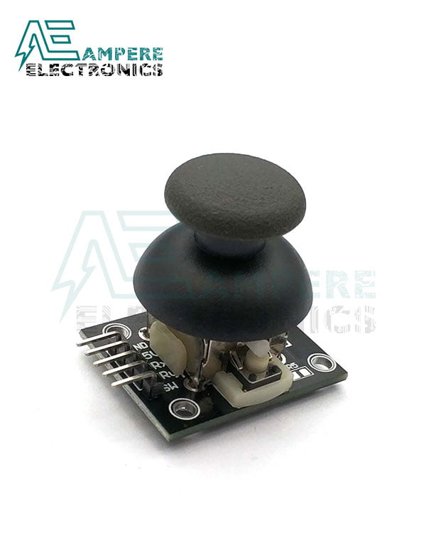


Dual Axis PS2 Joystick Module For Arduino
From the shop's description
Dual Axis PS2 Joystick Module For Arduino Two independent Potentiometer: one for each axis ( X and Y) Auto return to center position Low weight Cup-type Knob Compatible to interface with Arduino or with most microcontrollers Specifications Operating Voltage: 5V Internal Potentiometer value: 10k 2.54mm pin interface leads Dimensions: 1.57 in x 1.02 in x 1.26 in (4.0 cm x 2.6 cm x 3.2 cm) Operating temperature: 0 to 70 ?C Pin Configuration Pin No. Pin Name Description 1 Gnd Ground terminal of Module 2 +5v Positive supply terminal of Module 3 VRx Voltage Proportional to X axis 4 VRy Voltage Proportional to Y axis 5 SW Switch Internal Structure The below image is the? internal diagram of a Joystick Module . It consists of two? Potentiometer , each for one axis (X and Y). Both 10k potentiometer are independent to move in their particular direction. SW (Switch) pin is connected to a push button internally. Where Joysticks Are Used? When we listen the word ? Joystick ? we think of Game controllers. If we talk about Electronics there are many useful application of Joystick. These type of module are mostly used in? Arduino ?based DIY projects and Robot Control. As we know, the module gives analog output so it can be used for feeding the analog input based on direction or movement. It can also be connected to a movable camera to control its movement. How to Use Joystick? We can use a Joystick Module with Arduino, Raspberry Pi and any other Micro-controllers. We just have to connect the axis Pins VRx and VRy to the ADC Pins of the micro-controller. If you want to use the switch then connect it to the digital Pin of the Micro-controller. Follow the below block diagram to connect Joystick Module with Microcontroller. As used in many projects, the interfacing diagram of? Joystick Module with the Arduino ?is given below. It helps you to connect the joystick Module with Arduino and get the analog output based on the direction of movement of Joystick Knob. After Interfacing Joystick Module with the Arduino, we will get the analog output. The output range is fixed for each direction. The below image shows, the value of analog output for X and Y axis based on the movement of Joystick Module in all four directions (+X, -X, +Y, -Y). You will also get some analog value when moving the knob diagonally. Application Camera Pan/Tilt Control Game Input/Control Robot Control Analog Input of Parameters Widely use in DIY projects 2D-model Datasheet: Joystick Module Datasheet Related Products: SENSORS | MODULES
Read moreShow less
Similar products
 PS2 Joystick Module Breakout Sensor High QualityEGP 381 shopPrice may be out of date (74 days)
 I2C Bi-Directional logic Level Converter 4 Channel High QualityEGP 351 shopPrice may be out of date (74 days)
 SW-420 Vibration Switch ModuleEGP 351 shopchecked 17 days ago
 USB Type C Female PCB Connector Breakout Module 12pinEGP 351 shopPrice may be out of date (74 days)
 PAM8403 Stereo Audio Amplifier Module 2x3WEGP 35 – 702 shopschecked 15 days ago
 USB 3.0 Female Mother Head DIP Board moduleEGP 351 shopPrice may be out of date (74 days)
 TDA2030 Audio Amplifier Module 18W 6-12VEGP 35 – 504 shopschecked 15 days ago
- Kit NE555 Duty Cycle Adjustable Module Square Wave Signal GeneratorEGP 351 shopchecked 16 days ago