


MAX7219 8X8 Dot LED Matrix Display Module FC-16 (Solder)
Part number MAX7219
From the shop's description
The MAX7219 is compact, serial input/output common-cathode display drivers that interface microprocessors to 7-segment numeric LED displays of up to 8 digits or 64 individual LEDs. It includes an on-chip BCD code-B decoder, multiplex scan circuitry, segment and digits drivers, and an 8×8 static RAM that stores each digit. Only one external resistor is required to set the segment current for all LEDs. Features MAX7219 Driver Board A single module can drive an 8*8 common cathode matrix Module with input and output interface, supporting multiple module cascade 4 fixing screw holes, 3mm aperture , can be fixed with M3 copper column Specifications Input Voltage: 3.7 to 5.3 V Input Current: 320 mA Color: Blue , Red , Green Dimensions:3.2cm X 3.2cm X1.5cm Application Bar-Graph Displays 7-Segment Displays Industrial Controllers Electronic Panel Meters LED Matrix Displays Display of symbols, simple graphics and texts. Input Connector The header pins on the “ IN ” side is the main input connector. “ Vcc ” connects to 5V. Due to the fairly high current draw of the display (up to 250mA if the brightness is cranked all the way up), it is recommended to keep the brightness turned down to < 50% to avoid overheating the MCU voltage regulator if there are other peripherals also attached to this supply. “ GND ” connects to ground which needs to be common with the MCU. The other pins are for the SPI interface. “ DIN ” is the Data In. “ CS ” is Chip Select (sometimes labeled as LOAD) and “ CLK is the Clock pin. These lasts 3 pins are connected to any digital outputs on the microcontroller. Which pins they connect to is defined when an instance of the LedControl is created as shown in the program below. 1 x 5 Header VCC – Connect to 5V. GND – Connect to system ground. This ground needs to be in common with the MCU. DIN – Connect to any digital pin on MCU. CS / LOAD – Connect to any digital pin on <CU. CLK – Connect to any digital pin on MCU. Output Connector The break-out pins on the other end of the assembly are used if it is desirable to daisy-chain multiple displays. In this case, the “ DOUT ” is Data Out and it connects to the next modules “ DIN ” Data in pin. The other pins are passed straight-thru 1 x 5 Header VCC – Connect to 5V on next module if looping power through. GND – Connect to GND on next module DOUT – Connect to DIN on next module. CS / LOAD – Connect to CS / LOAD on next module CLK – Connect to CLK on next module PACKAGE INCLUDES: 1.3″ 8 x 8 dot matrix of red LEDs MAX7219 LED Driver board 8-pin female socket (x2) 5-pin right-angle male header 5-pin straight male header For arduino projects, check this version . Useful Links MAX7219 Datasheet
Read moreShow less
Similar products
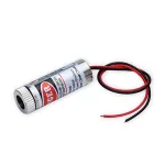 Red Laser Dot 5mw 3-6V 650nmEGP 1081 shopPrice may be out of date (74 days)
 AD22-22AM Round Shape Ammeter Green DisplayEGP 1101 shopchecked 11 days ago
 Laser Emitter Red Point 650nm 12VDC 5mWEGP 1101 shopchecked 20 days ago
 LED Light Kit 5mm 100 pcsEGP 1001 shopPrice may be out of date (74 days)
- Led Driver 50w 300mAEGP 1001 shopchecked 23 days ago
 WS2812 5050 RGB LED Driver Module Board 64 LEDEGP 100 – 2002 shopschecked 15 days ago
 OSEPP 10mm LEDs (2 x 6 colors) – LS-00044EGP 1001 shopPrice may be out of date (74 days)
 H11F2 MOSFET Output Analog FET Optocoupler IC DIP-6EGP 1001 shopchecked 15 days ago