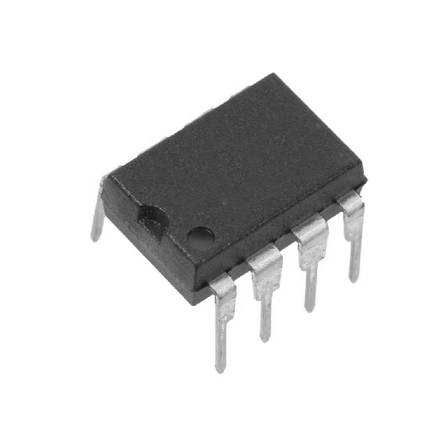
IR2117 High-Voltage High-Speed Single-Channel Gate Driver IC 600V DIP-8
Part number IR2117
From the shop's description
IR2117 High-Voltage High-Speed Single-Channel Gate Driver IC 600V DIP-8 The IR2117 is a high-voltage, high-speed power MOSFET and IGBT driver. Proprietary HVIC and latch-immune CMOS technologies enable ruggedized monolithic construction. The logic input is compatible with standard CMOS outputs. Features Floating channel designed for bootstrap operation Tolerant to negative transient voltage Gate drive supply range from 10V to 20V CMOS Schmitt-triggered inputs with pull-down Output in phase with input High pulse current buffer stage designed for minimum cross-conduction Logic input compatible with standard CMOS outputs Single-channel driver Specifications Parameter Value Conditions / Notes General Product Type High-voltage, high-speed power MOSFET and IGBT driver Single channel Part Number IR2117 8-lead PDIP package Lead-Free Part Number IR2117PbF Lead-free version Output Phase Output in phase with input IR2117 specific Input Type CMOS Schmitt-triggered input with pull-down Logic input compatible with standard CMOS outputs Output Driver High pulse current buffer stage Designed for minimum cross-conduction Floating Channel Designed for bootstrap operation Can be used to drive an N-channel power MOSFET or IGBT in high or low side configuration Key Ratings VOFFSET 600V max High-side floating supply offset voltage Gate Drive Supply Range 10V to 20V From datasheet features and product summary Output High Short-Circuit Pulsed Current (IO+) 200mA min, 250mA typ VO = 0V, VIN = Logic “1”, PW ≤ 10µs Output Low Short-Circuit Pulsed Current (IO-) 420mA min, 500mA typ VO = 15V, VIN = Logic “0”, PW ≤ 10µs Turn-On Propagation Delay, ton 125ns typ, 200ns max VS = 0V Turn-Off Propagation Delay, toff 105ns typ, 180ns max VS = 600V Turn-On Rise Time, tr 80ns typ, 130ns max Dynamic switching characteristic Turn-Off Fall Time, tf 40ns typ, 65ns max Dynamic switching characteristic Dynamic Test Conditions VBIAS (VCC, VBS) = 15V; CL = 1000pF; TA = 25°C Unless otherwise specified Recommended Operating Conditions VB, High-Side Floating Supply Voltage VS + 10V to VS + 20V Recommended operating condition VS, High-Side Floating Supply Offset Voltage 600V max Logic operational for VS of -5V to +600V; logic state held for VS of -5V to -VBS VHO, High-Side Floating Output Voltage VS to VB Recommended operating condition VCC, Logic Supply Voltage 10V to 20V Recommended operating condition VIN, Logic Input Voltage 0V to VCC Recommended operating condition Ambient Temperature, TA -40°C to +125°C Recommended operating condition Allowable Offset Supply Voltage Transient, dVs/dt 50 V/ns Maximum rating Static Electrical Characteristics Input Logic “1” Voltage, VIH 9.5V min IR2117 logic “1” Input Logic “0” Voltage, VIL 6.0V max IR2117 logic “0” High-Level Output Voltage Drop, VBIAS – VO 100mV max IO = 0A Low-Level Output Voltage, VOL 100mV max IO = 0A Offset Supply Leakage Current, ILK 50µA max VB = VS = 600V Quiescent VBS Supply Current, IQBS 50µA typ, 240µA max VIN = 0V or VCC Quiescent VCC Supply Current, IQCC 70µA typ, 340µA max VIN = 0V or VCC Logic “1” Input Bias Current, IIN+ 20µA typ, 40µA max VIN = VCC Logic “0” Input Bias Current, IIN- 1.0µA max VIN = 0V VBS Undervoltage Positive-Going Threshold, VBSUV+ 7.6V min, 8.6V typ, 9.6V max VBS supply undervoltage threshold VBS Undervoltage Negative-Going Threshold, VBSUV- 7.2V min, 8.2V typ, 9.2V max VBS supply undervoltage threshold VCC Undervoltage Positive-Going Threshold, VCCUV+ 7.6V min, 8.6V typ, 9.6V max VCC supply undervoltage threshold VCC Undervoltage Negative-Going Threshold, VCCUV- 7.2V min, 8.2V typ, 9.2V max VCC supply undervoltage threshold Absolute Maximum Ratings VB, High-Side Floating Supply Voltage -0.3V to 625V Absolute maximum rating VS, High-Side Floating Supply Offset Voltage VB – 25V to VB + 0.3V Absolute maximum rating VHO, High-Side Floating Output Voltage VS – 0.3V to VB + 0.3V Absolute maximum rating VCC, Logic Supply Voltage -0.3V to 25V Absolute maximum rating VIN, Logic Input Voltage -0.3V to VCC + 0.3V Absolute maximum rating Junction Temperature, TJ 150°C max Absolute maximum rating Storage Temperature, TS -55°C to +150°C Absolute maximum rating Lead Temperature 300°C max Soldering, 10 seconds Package and Thermal Data (8-Pin PDIP) Package Type 8-Lead PDIP Through-hole package Package Power Dissipation, PD 1.0W TA ≤ +25°C Thermal Resistance, Junction-to-Ambient, RthJA 125°C/W Board-mounted, still-air conditions Applications High-voltage, high-speed power MOSFET gate driving High-voltage, high-speed IGBT gate driving N-channel power MOSFET or IGBT drive in high-side configuration N-channel power MOSFET or IGBT drive in low-side configuration Package Content 1 x IR2117 High-Voltage High-Speed Single-Channel Gate Driver IC 600V DIP-8 DataSheet IR2117
Read moreShow less
Similar products
 X2816AD IC EEPROM 2KX8 MOS DIP 24PinEGP 701 shopchecked 15 days ago
 HT12D 12-Bit Encoder PDIP-18EGP 701 shopchecked 20 days ago
 HT-12E 12-Bit Encoder IC DIP-18EGP 701 shopchecked 20 days ago
 uA709 Operational Amplifier IC DIP-14EGP 701 shopchecked 17 days ago
 IR2118 Single High Side Gate Driver 20V 420mA IC PDIP-8EGP 701 shopchecked 28 days ago
 IR2103 Half Bridge 2 210mA 100ns 50ns 10V~20V 360mA PDIP-8 Gate Driver ICEGP 651 shopchecked 16 days ago
 μPD416C-3 Dynamic RAM 16K 16 Pin DIPEGP 751 shopchecked 17 days ago
 8088 IC 8-BIT HMOS MICROPROCESSOREGP 751 shopchecked 20 days ago