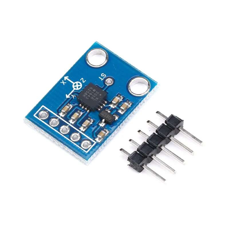
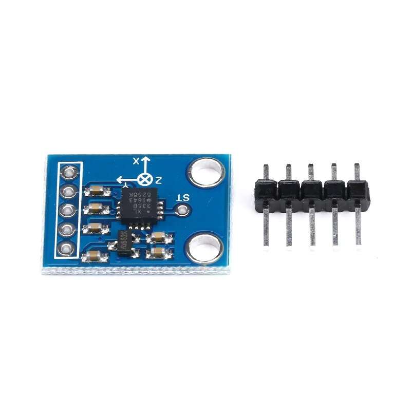
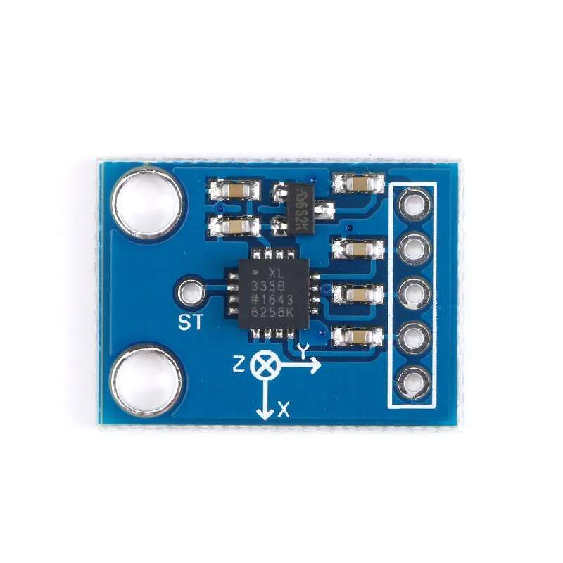
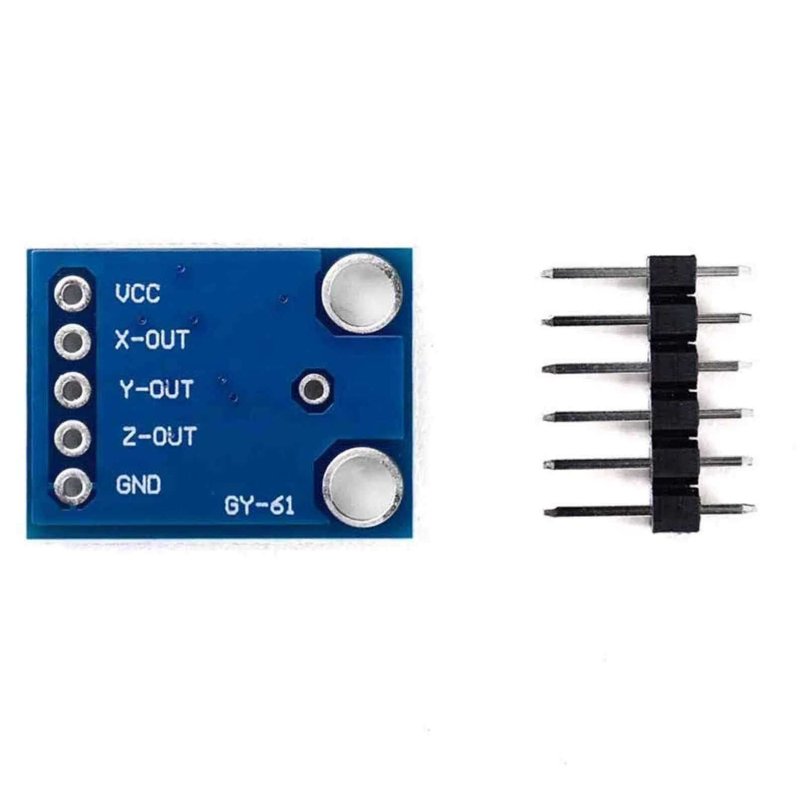
ADXL335 3-axis Accelerometer Module
Part number ADXL335
From the shop's description
At the heart of the module is a small, low-power 3-axis MEMS accelerometer from Analog Devices with extremely low noise – ADXL335 . The sensor has a full sensing range of ±3 g. It can measure the static acceleration due to gravity in tilt-sensing applications, as well as dynamic acceleration resulting from motion, shock, or vibration. The sensor works on power between 1.8V to 3.6VDC (3.3V optimal), and typically consumes just 350µA of current. However, an on-board 3.3V regulator makes it a perfect choice for interfacing with 5V microcontrollers such as the Arduino. This breadboard friendly board breaks out every pin of the ADXL335 to a 6-pin, 0.1″ pitch header. This includes 3 analog outputs for X, Y and Z axis measurements, 2 supply pins and a self-test pin which allows you to check the functioning of the sensor in the final application. The analog outputs are Ratiometric , meaning 0g measurement output is nominally equal to half of the 3.3V supply voltage (1.65V), -3g is at 0v and 3g is at 3.3V with full scaling in between. Here are the complete specifications of ADXL335 Accelerometer IC. Operating Voltage 1.8V – 3.6V Operating Current 350μA (typical) Sensing Range ±3g (Full Scale) Temperature Range −40 to +85°C Sensing axis 3 axis Sensitivity 270 to 330mV/g (Ratiometric) Shock Resistance Up to 10,000g Board Dimension 20mm x 15mm ADXL335 Accelerometer Pinout Before diving into hookup and example code, let’s first take a look at its Pinout. VCC pin provides power for the accelerometer which can be connected to 5V on the Arduino. X-Out pin outputs analog voltage proportional to acceleration exerted on X axis. Y-Out pin outputs analog voltage proportional to acceleration exerted on Y axis. Z-Out pin outputs analog voltage proportional to acceleration exerted on Z axis. GND pin is connected to GND on Arduino ST(Self-Test) pin controls the self-test feature. This feature is discussed in detail at the end. Wiring ADXL335 Accelerometer to Arduino UNO Now that we have a complete understanding of how the ADXL335 accelerometer works, we can begin hooking it up to our Arduino. Connections are pretty easy. Start by placing the accelerometer on to your breadboard. Connect the VCC pin to the 5V pin on the Arduino and connect the GND pin to the Ground pin on the Arduino. Also connect X, Y and Z output to the analog pins A0, A1, and A2 on Arduino. For accurate results, we need to change the analog reference(AREF) voltage of the Arduino. This can be done by connecting the 3.3V pin on Arduino to the AREF pin. When you’re done you should have something that looks similar to the illustration shown below. Wiring ADXL335 Accelerometer Module to Arduino UNO Arduino Code – Reading ADXL335 accelerometer
Read moreShow less
Similar products
 INMP441 MEMS Microphone - I2SEGP 1801 shopchecked 17 days ago
 AHT10 High Precision Digital Temperature and Humidity Sensor ModuleEGP 1801 shopPrice may be out of date (74 days)
 IMU (3 Axis Gyro + 3 Axis Accelorometer ) renovate MPU-6050EGP 1801 shopchecked 16 days ago
 3 Axis Digital Gyroscope Sensor ModuleEGP 1801 shopPrice may be out of date (74 days)
 DHT22/AM2302 Digital Temperature & Humidity SensorEGP 1801 shopPrice may be out of date (74 days)
 20Kg Load Cell Weight SensorEGP 1801 shopchecked 19 days ago
 Line Follower Sensor TCRT5000 (5 Channels)EGP 181.991 shopchecked 25 days ago
- PR08-2DN Inductive Proximity Switch NPN NOEGP 1751 shopchecked 14 days ago